Operating Instructions ACTIVE 06/07182
182 Operating Instructions ACTIVE 06/07
17 Special Functions
The configurable functions of the corresponding control methods enable another field
of application of the frequency inverters. The integration in the application is made
easier by special functions.
17.1 Pulse Width Modulation
The motor noises can be reduced by changing over the parameter
Switching Fre-
quency
400. The maximum reduction of the switching frequency should not exceed a
ratio of 1:10 to the frequency of the output signal for a sine-shaped output signal. The
maximum possible switching frequency depends on the drive output and the ambient
conditions. For the required technical data refer to the corresponding table and the
device type diagrams.
Parameter Settings
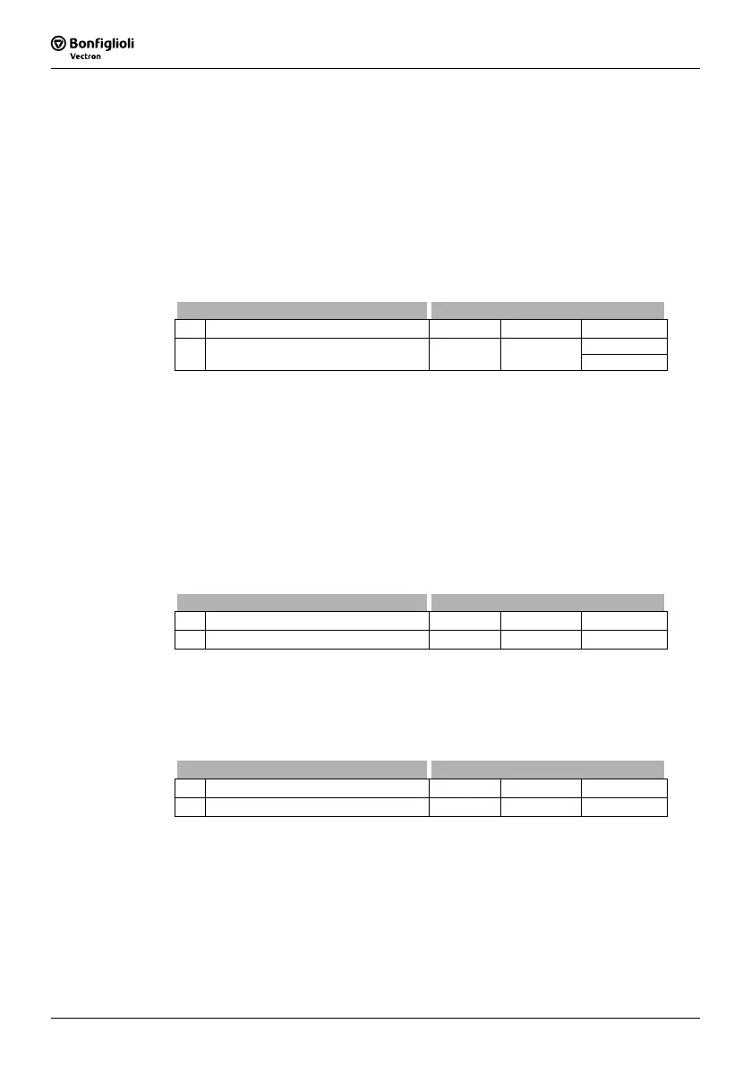
No. Description Min. Max. Fact. sett.
2 kHz
1)
400 Switching frequency 2 kHz 16 kHz
4 kHz
2)
The factory setting of parameter Switching frequency 400 depends on the setting of parameter
Configuration 30:
1)
configurations 1xx
2)
configurations 2xx / 4xx/ 5xx
The heat losses increase proportionally to the load point of the frequency inverter and
the switching frequency. The automatic reduction adjusts the switching frequency to
the current operating state of the frequency inverter in order to provide the output
performance required for the drive task at the greatest possible dynamics and a low
noise level.
The switching frequency is adjusted between the limits which can be set via parame-
ters
Switching frequency 400 and Min. Switching Frequency 401. If the Min. Switch-
ing Frequency
401 is larger than or equal to the Switching Frequency 400, the
automatic reduction is deactivated.
Parameter Settings
No. Description Min. Max. Fact. sett.
401 Min. Switching Frequency 2 kHz 16 kHz 2 kHz
The change of the switching frequency depends on the heat sink temperature switch-
off limit and the output current.
The temperature limit to be exceeded so that the switching frequency is reduced can
be set via parameter
Reduction Limit Heat Sink Temp. 580. If the heat sink tempera-
ture falls below the threshold set via parameter
Reduction Limit Heat Sink Temp. 580
by 5 °C, the switching frequency is increased again step by step.
Parameter Settings
No. Description Min. Max. Fact. sett.
580 Reduction Limit Heat Sink Temp. -25 °C 0 °C -4 °C
Note: The limit for the switching frequency reduction is influenced by the
intelligent current limits depending on the selected
Operation Mode
573 and the output current. If they have been switched off or provide
the full overload current, the switching frequency is reduced when the
output current exceeds the limit of 87.5% of the long-term overload
current (60s). The switching frequency is increased if the output cur-
rent drops below the reference current of the next highest switching
frequency.

 Loading...


