Operating Instructions ACTIVE06/07 181
06/07 Operating Instructions ACTIVE 181
The percentage setting of the
Reference Modulation 750 is basically depending on
the leakage inductivity of the machine. The default value was selected such that in
most cases the remaining deviation of 5% is sufficient as a reserve range for the cur-
rent controller. For the optimization of the controller parameters, the drive is acceler-
ated with a flat ramp into the area of field weakening, so that the modulation control-
ler intervenes. The limit is set via parameter
Reference Modulation 750. Then, the
control loop can be excited with a unit step function by modifying the reference
modulation (change-over between 95% and 50%). By means of an oscillographed
measurement of the flux-forming current component on the analog output of the fre-
quency inverter, the controlling process of the modulation controller can be assessed.
The course of the signal of the flux-forming current I
sd
should reach the stationary
value after overshooting without oscillation. An oscillating of the course of the current
can be damped by increasing the integral time. The parameter
Integral Time 752
should roughly correspond to the actual value
Act. Rotor Time Constant 227.
16.5.6.1 Limitation of Modulation Controller
The output signal of the modulation controller is the internal reference flux. The con-
troller output and the integrating part are limited via the parameter
Reference Imr
Lower Limit
755 and the product of Rated Magnetizing Current 716 with Reference
Flux
717. The magnetizing current parameter forming the upper limit is to be set to
the rated value of the machine. For the lower limit, select a value which also builds up
an adequate flux in the machine in the field weakening area. The limitation of the
control deviation at the output of the modulation controller prevents a possible oscilla-
tion of the control loop in the case of load surges. The parameter
Control Deviation
Limitation
756 is stated as an absolute value and acts both as a positive and a nega-
tive limit.
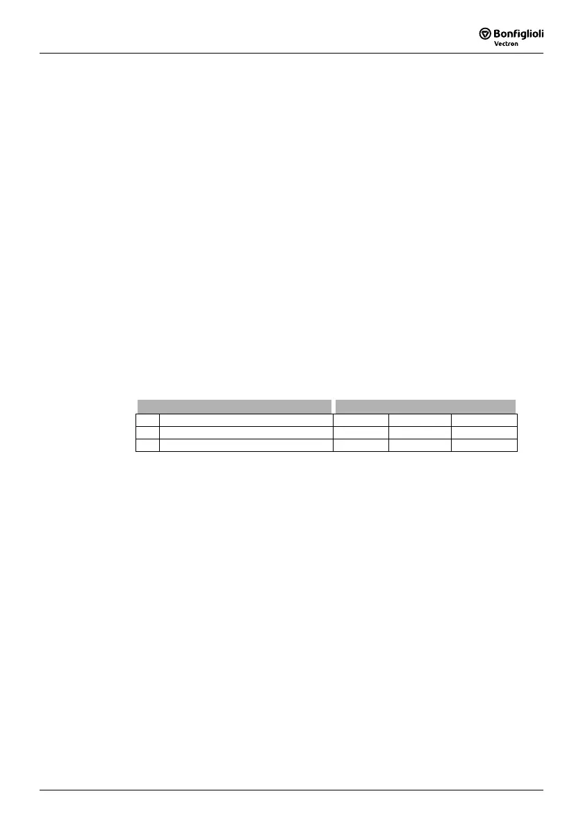
Parameter Settings
No. Description Min. Max. Fact. sett.
755 Reference Imr Lower Limit 0.01
⋅I
FIN
o ⋅ I
FIN
0.01⋅I
FIN
756 Control Deviation Limitation 0.00 % 100.00 % 10.00 %

 Loading...


