Operating Instructions ACTIVE06/07 171
06/07 Operating Instructions ACTIVE 171
16.4 Functions of Sensorless Control
The configurations of the sensor-less control contain the following additional func-
tions, which supplement the behavior according to the parameterized V/f characteris-
tic.
16.4.1 Slip compensation
The load-dependent difference between the reference speed and the actual speed of
the 3-phase motor is referred to as the slip. This dependency can be compensated by
the current measurement in the output phases of the frequency inverter.
The activation of Operation Mode 660 for the slip compensation enables speed con-
trol without feedback. The stator frequency and speed are corrected depending on the
load. Before the slip compensation can be activated, the guided commissioning has to
be carried out. The
Stator Resistance 377 is required to ensure a correct function and
is measured during the guided commissioning.
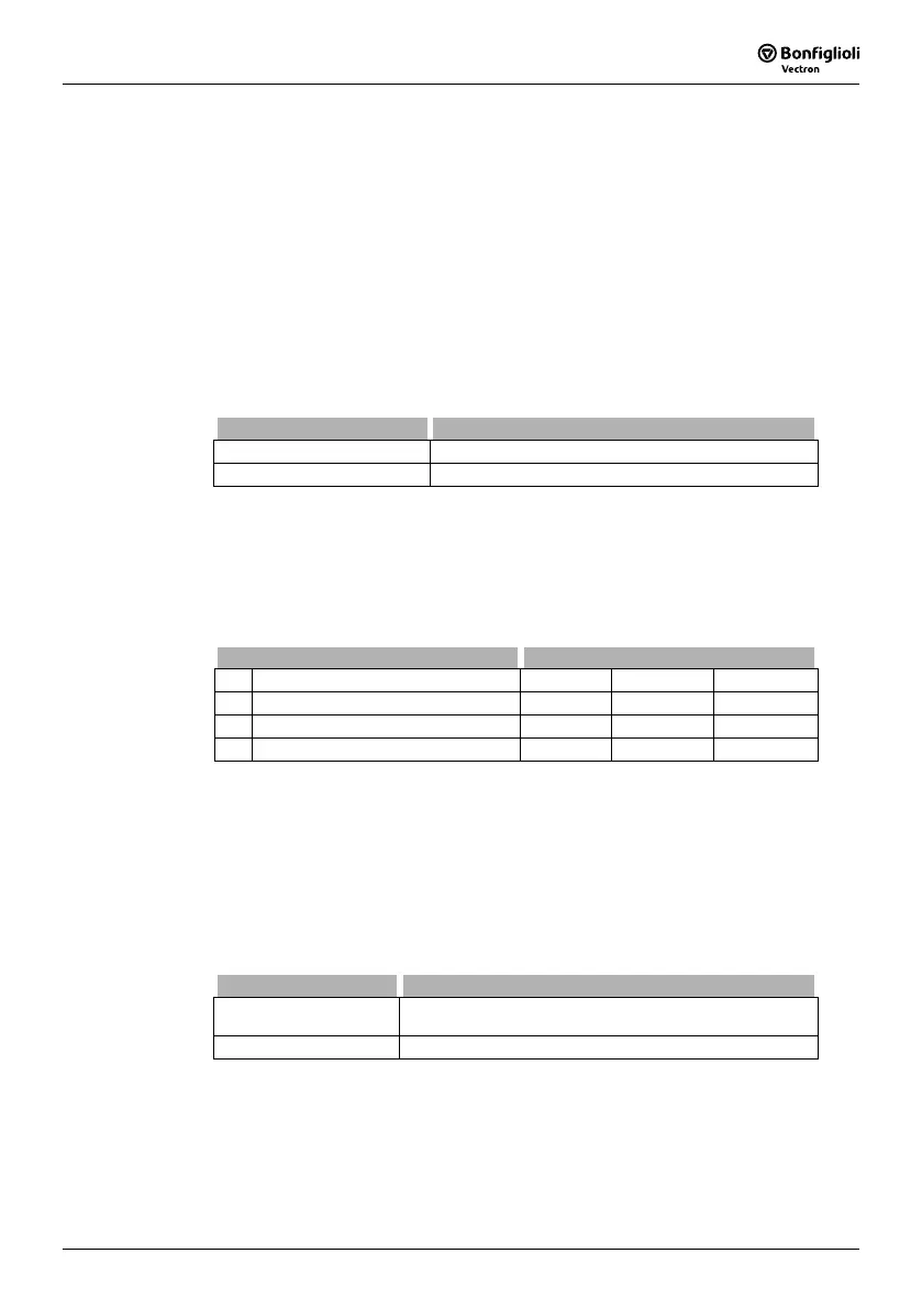
Operation mode 660 Function
0 - Off The slip compensation is deactivated.
1 - Switched on The load-dependent slip speed is compensated.
The control behavior of the slip compensation can only be optimized via the parame-
ters in the case of specific applications. The parameter
Amplification
661 determines
the correction of the speed and the effect of the slip compensation proportionally to
the change of load. The
Max. Slip Ramp 662 defines the max. frequency change per
second in order to avoid an overload in the case of a load change.
The parameter
Minimum Frequency
663 determines the frequency as from which the
slip compensation becomes active.
Parameter Settings
No. Description Min. Max. Fact. sett.
661 Amplification 0.0 % 300.0 % 100.0 %
662 Max. Slip Ramp 0.01 Hz/s 650.00 Hz/s 5.00 Hz/s
663 Minimum Frequency 0.01 Hz 999.99 Hz 0.01 Hz
16.4.2 Current limit value controller
Via a load-dependent speed control, the current limit controller ensures that the drive
system is not overloaded. This is extended by the intelligent current limits described in
the previous chapter. The current limit value controller reduces the load on the drive,
e.g. during acceleration, by stopping the acceleration ramp. The switch-off of the
frequency inverter which happens when the acceleration ramps have been set at an
excessive gradient is prevented in this way.
The current limit value controller is switched on and off via parameter
Operation
Mode
610.
Operation Mode 610 Function
0 - Off
The current limit controller functions and the intelligent
current limits have been deactivated.
1 - Switched on The current limit controller is active.
Behavior in motor operation:
If the current set via parameter
Current Limit 613 is exceeded, the activated current
limit controller will reduce the output frequency until the current limit is no longer
exceeded. The output frequency is reduced, as a maximum, to the frequency set by
parameter
Frequency Limit 614. If the current is below the Current Limit
613, the
output frequency increases to the reference value again.

 Loading...


