Operating Instructions ACTIVE06/07 151
06/07 Operating Instructions ACTIVE 151
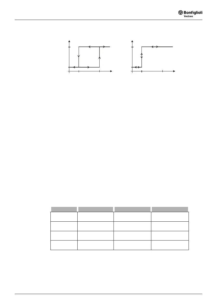
The setting of the percentage limits of the comparators enables the following logical
links. The comparison with signs is possible in the corresponding operation modes of
the comparators.
1
on
above
0
off
below
%
1
on
above
0
off
below
%
14.5.3 Logic Modules
With the Logic Modules function, it is possible to link external digital signals and inter-
nal logic signals of the frequency inverter to one another. Four identical logic modules
are available. These modules can be parameterized independent of one another. The
results of the logic operations can be used for further functions within and outside of
the frequency inverter. In addition to the combinatory logic functions AND, OR and
EXOR, the sequential logic functions RS flip-flop, D flip-flop and Toggle flip-flop are
available.
Each module has two logic inputs and one logic output. The inputs can be parameter-
ized and can be assigned to different signal sources. The signal sources are listed in
the logic table in chapter "Digital Inputs". Additionally, the logic modules can be inter-
connected to each other via the corresponding parameterization. The functionality of
the parameters is the same in each of the four logic modules.
Note: The logic modules are processed internally in the frequency inverter one
after the other depending on their number. For example, logic module 1
is processed before logic module 2.
When designing application-specific logic links, e.g. in the case of time-
critical applications:
− Make sure to comply with the correct order of the logic modules.
− Observe the processing time of 16 ms.
The following table shows the assignment of the parameters to the individual logic
modules:
Module Operation mode Input 1 Input 2
Logic module 1
Operation Mode
Logic 1
198
Input 1 Logic 1 199 Input 2 Logic 1 200
Logic module 2
Operation Mode
Logic 2
201
Input 1 Logic 2 202 Input 2 Logic 2 203
Logic module 3
Operation Mode
Logic 3
205
Input 1 Logic 3 206 Input 2 Logic 3, 207
Logic module 4
Operation Mode
Logic 4
503
Input 1 Logic 4 504 Input 2 Logic 4 505

 Loading...


