Operating Instructions ACTIVE 06/07152
152 Operating Instructions ACTIVE 06/07
The parameters
Operation Mode Logic 1 198, Operation Mode Logic 2 201, Opera-
tion Mode Logic 3
205 and Operation Mode Logic 4 503 include the following func-
tions:
Operation mode Function
0 - Off Signal output is switched off.
1 - AND
Input 1 and input 2 are linked to each other via a logic AND
operation.
2 - OR
Input 1 and input 2 are linked to each other via a logic OR
operation.
3 - XOR
Input 1 and input 2 are linked to each other via a logic Ex-
clusive OR operation. Output Q will be logic "1" only if differ-
ent logic levels are present at input 1 and input 2.
10 - RS Flip-Flop
Input 1 is the set input,
input 2 is the reset input of the RS flip-flop.
Logic "1" at the set input will set output Q to "1". Logic "1"
at the reset input will set output Q to "0".
If logic "0" is present at both inputs, the output signal is kept
at the last status.
20 - Toggle Flip-Flop
The output signal changes with the positive edge of the clock
signal at input 1.
Input 2 is wired internally in this configuration.
30 - D Flip-Flop
If a positive clock edge is received at input 2 (clock pulse
input C), the signal present at input 1 (data input D) is
transmitted to output Q.
Examples of the logic functions depending on the selected operation mode:
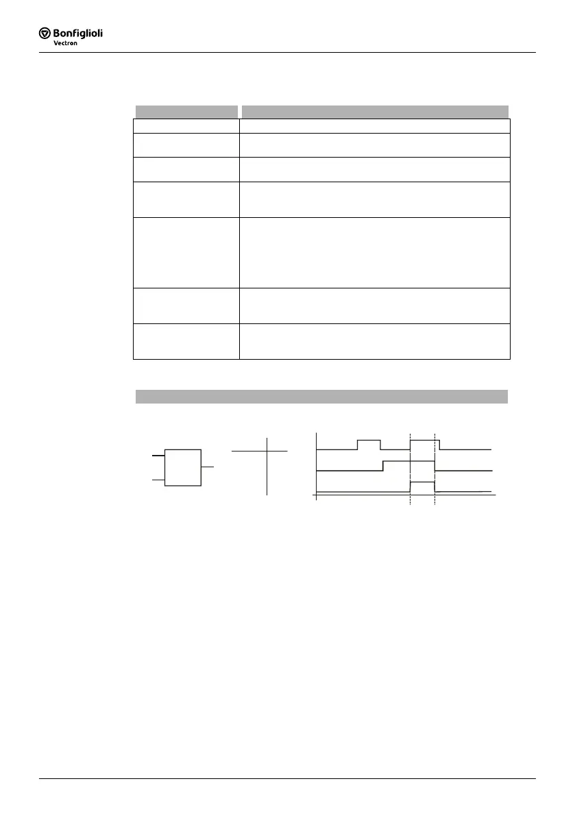
AND Operation
Parameter
Operation Mode Logic = 1
E1
E2
Q
E1
E2 Q
0
0
1
1
0
1
0
1
0
0
0
1
Q
E1
E2
&
E1: input 1; E2: input 2; Q: output
If logic "1" is present at input 1 and input 2, output Q is logic "1". If both inputs or
either one input are logic "0", output Q will be logic "0", too.

 Loading...


