ASSEMBLY
1. Attaching
the
feed mechanism assembly
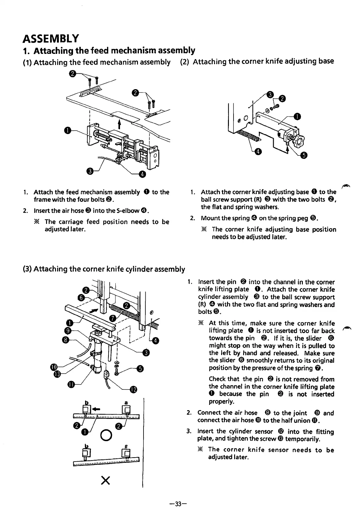
1.
Attach the feed
mechanism
assembly
0
to
the
frame
with
the four bolts@.
2.
Insert the air hose@ into the S-elbow
e.
*
The
carriage feed position needs
to
be
adjusted later.
(2) Attaching
the
corner knife adjusting
base
1.
Attach the corner knife adjusting
base
0
to
the
ball
screw
support
(R)
@
with
the
two
bolts
@,
the flat and spring
washers.
2. Mount the
springe
on
the spring peg
@).
*
The
corner knife adjusting
base
position
needs
to
be
adjusted later.
(3) Attaching
the
corner
knife
cylinder assembly
~;~
9J
~-~
~--------------------
X
1.
Insert the pin @ into the channel in the corner
knife lifting plate
0.
Attach the corner knife
cylinder
assembly
@to
the ball screw support
(R)
e
with
the
two
flat
and spring
washers
and
bolts@.
*
At
this time, make sure the corner knife
lifting plate
0
is
not inserted
too
far
back
towards the pin
@.
If
it
is,
the slider
€)
might stop on the way when
it
is
pulled
to
the
left
by hand and
released.
Make
sure
the slider
€)
smoothly returns
to
its original
position by the
pressure
of
the spring & .
Check
that the pin
@is
not removed from
the channel in the corner knife lifting plate
0
because
the pin @
is
not
inserted
properly.
2.
Connect the air
hose
@)
to
the
joint
@)
and
connect the air
hose
«@
to
the half union
4D.
3.
Insert the cylinder
sensor
0 into the
fitting
plate,
and
tighten the
screw~
temporarily.
-33-
* The
corner
knife
sensor needs
to
be
adjusted later.
From the library of: Superior Sewing Machine & Supply LLC