3-38
Confidential
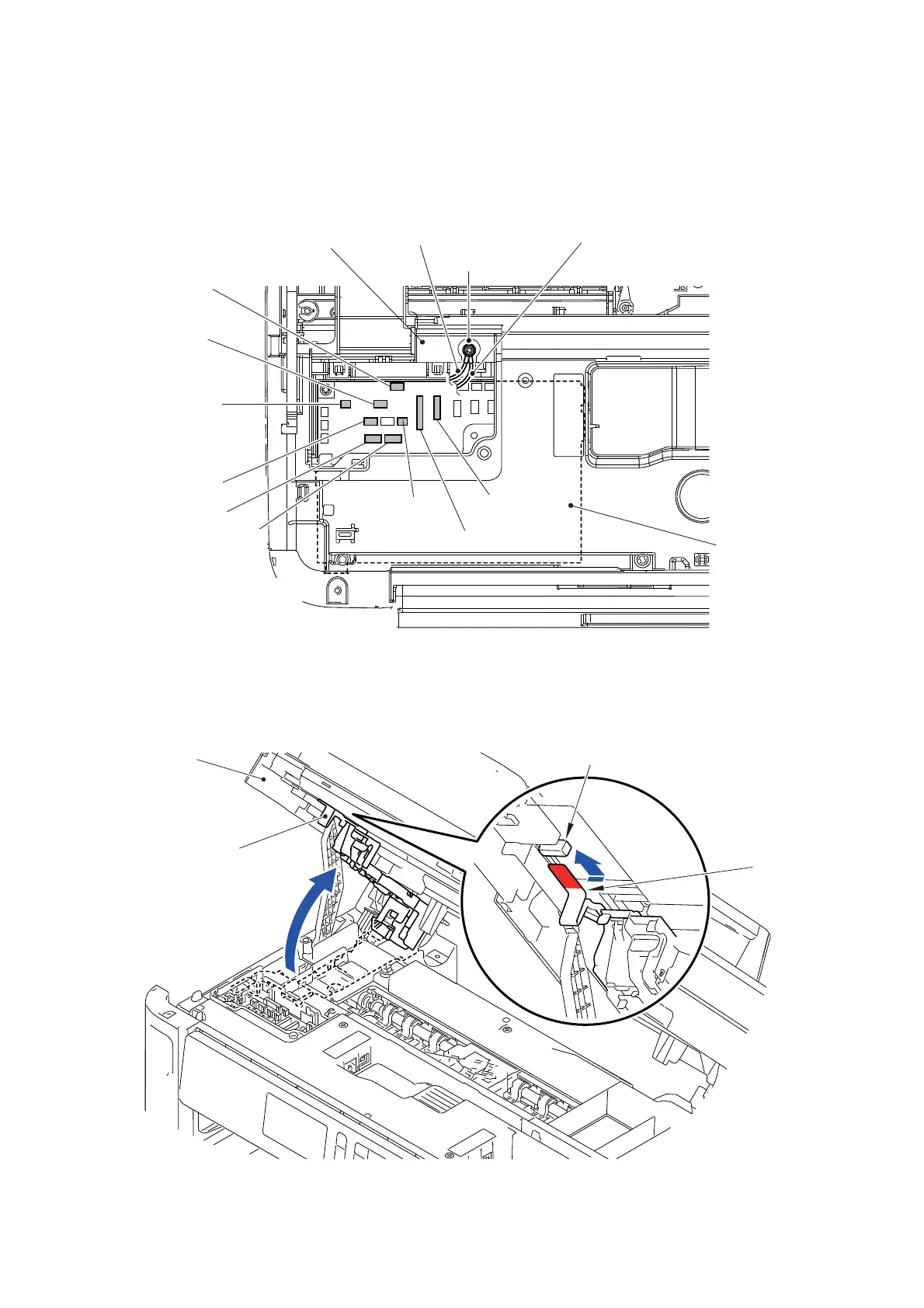
(3) Disconnect the seven Connectors from the Main PCB.
(4) Disconnect the two Flat cables from the Main PCB.
(5) Remove the screw (SCREW BIND M3x6) and remove the ADF FG wire and FB
FG wire from the Main PCB frame.
Fig. 3-12
(6) Lift the Harness holder and secure the Hook of the Harness holder to the slot on
the Document scanner unit.
Fig. 3-13
Main PCB
ADF document
FB FG wire
SCREW BIND M3x6
ADF FG wire
Document scanning
Document cover
MP paper detection
ADF motor harness
FB motor harness
ADF cover
First side CIS flat cable
Second side CIS
sensor harness
flat cable
sensor harness
Main PCB frame
detection sensor
harness
position sensor
harness ASSY
sensor harness
Harness holder
Hook
Document
scanner unit
Slot of the document scanner unit
Hook
 Loading...