3-104
Confidential
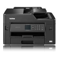
(11)Remove the screw (TAPTITE CUP S M3x6) from the CR frame ASSY.
Assembling Note:
Tighten the screw (TAPTITE CUP S M3x6) temporarily and then
perform the following procedures before mounting the Upper cover.
1) Mount the Head/carriage unit and CR timing belt to the CR frame ASSY.
2) Tighten the one screw (TAPTITE CUP S M3x6) firmly.
(12)Remove the Belt tension spring from the CR frame ASSY.
Fig. 3-123
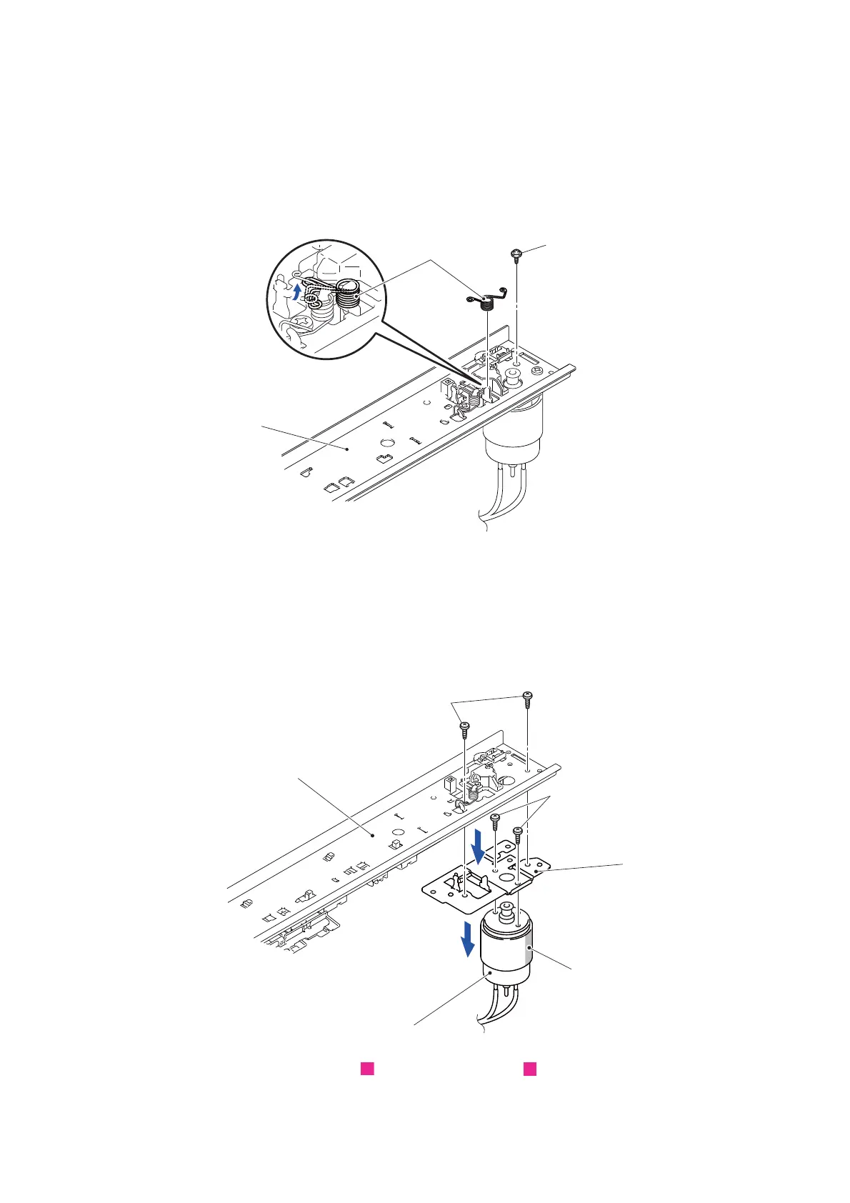
(13)Remove the two screws (SCREW BIND M3x6) and remove the Motor plate from
the CR frame ASSY.
(14)Remove the two screws (SCREW BIND M3x6) and remove the Carriage motor
from the Motor plate.
Assembling Note: Assemble the carriage motor in a way that the print section comes
to the position shown in the figure.
Fig. 3-124
Routing of harnesses: See “ Lower side cover”, “ Carriage motor harness/ASF
motor harness ASSY”.
TAPTITE CUP S M3x6
Belt tension spring
CR frame ASSY
SCREW BIND M3x6
CR frame ASSY
Motor plate
Print section
Carriage motor
SCREW BIND M3x6
13
14
13
20
 Loading...