III - 47
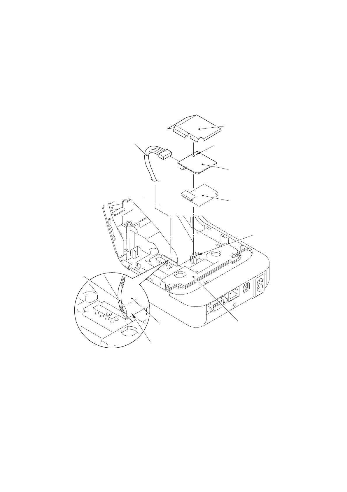
[9] Installing the PCB WYSAGBUX7-1 05
(1) Connect the WLAN harness ASSY onto the PCB WYSAGBUX7-1 05.
(2) Pass the WLAN harness ASSY through the hole on the under cover.
(3) Set the WIFI cover B, the PCB WYSAGBUX7-1 05 and the WIFI cover A onto the
under cover.
CAUTION: Confirm that the pin are properly inserted into the positioning hole of
the PCB WYSAGBUX7-1 05.
Fig. 3.5-28 Installing the PCB WYSAGBUX7-1 05
WLAN harness ASSY
PCB WYSAGBUX7-1 05
Pin
Under cover
Hole
Flat cable of
the head ASSY
WLAN harness ASSY
Positioning hole
WIFI cover A
WIFI cover B
 Loading...