6. ASSEMBLY
SL-710A
29
6. ASSEMBLY
DANGER
Wait at least 10 minutes after turnin
ower switch and disconnectin
ower cord from the wall outlet
before o
late of the control box. Touchin
resent can result in
severe injury.
CAUTION
Disassembl
ualified
technician.
Turn off the
ower switch and disconnect the
ower cord from the wall outlet before assembl
,
otherwise the machine ma
erate if the treadle
is de
mistake, which could result in
injury.
If the
ower switch needs to be left on when
carr
careful to observe all safety precautions.
Use both hands to hold the machine head when
tilting it back or returning it to its original position. If
onl
one hand is used, the wei
our hand
may get caught.
Be sure to wear
our skin, otherwise
inflammation can result.
Furthermore, do not drink the oil under an
and
diarrhea.
Keep the oil out of the reach of children.
Use onl
arts as
specified by Brother.
If an
devices have been removed, be
absolutel
sure to re-install them to their ori
ositions and check that the
before using the machine.
An
eration which result
from unauthorized modifications to the machine
will not be covered by the warranty.
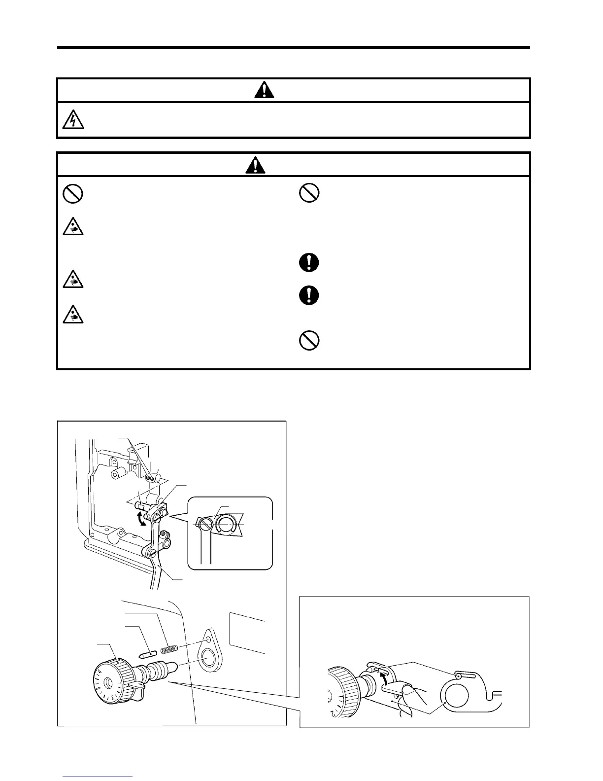
6-1. Stitch length dial, reverse stitching lever and
feed regulator mechanism
1. Insert the feed regulator assembly (1) into the
mounting hole in the arm so that the screw stop is
facing to the front.
2. Check that the feed regulator (2) moves smoothly with
no play in the direction of the arrow, and then tighten
the two set screws (3).
3. Set the feed regulator (2) so that it is horizontal as
shown in figure [A], insert the spring (4) and the
positioning pin (5) into the mounting hole, and then
screw in the stitch length dial (6).
< For DD7100A, 710A >
The positioning pin (5) should be in the groove of the
lock lever (7) when screwing in the stitch length dial (6).
1708M
(5)
(7)
1707M
1706M
(3)
[2 pcs.]
(2)
(4)
(5)
(6)
Screw stop
(2)
(1)
[A]
Horizontal