7. ADJUSTMENTS
SL-710A
68
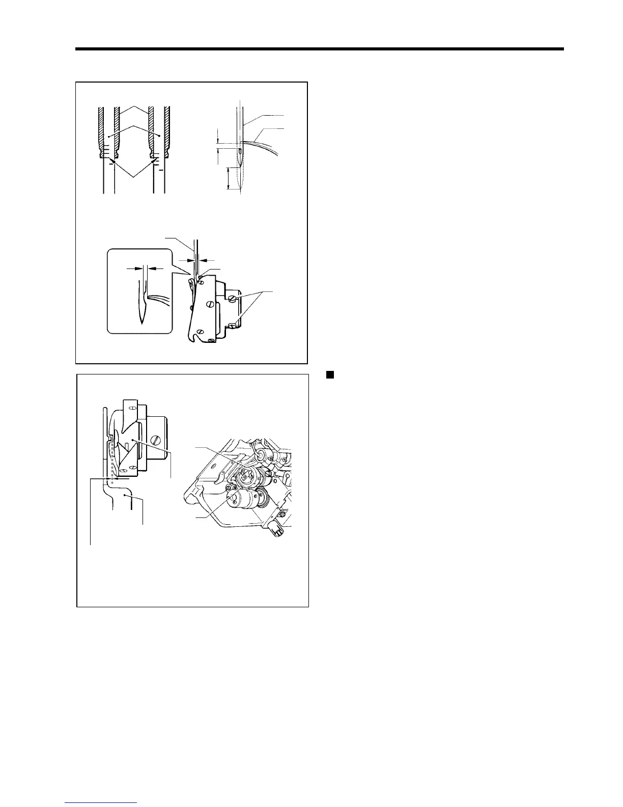
7-8. Adjusting the needle and rotary hook timing
The tip of the rotary hook (3) should be aligned with the
center of the needle (4) when the needle bar (1) moves
up from its lowest position to the position where reference
line (b), which is the line at the bottom of the needle bar
(1) (third line from the bottom when using a DA X 1
needle), is aligned with the lower edge of the needle bar
bush D (2) as shown in the illustration.
1. Turn the machine pulley to raise the needle bar (1)
from its lowest position until reference line (b) is
aligned with the lower edge of the needle bar bush D
(2) as shown in the illustration.
(The needle should rise by 1.8 mm [2.2 mm for -[][] 5
specifications]
and the distance from the needle hole
to the tip of the rotary hook should be 0 - 0.5 mm.)
2. Loosen the set screws (5), and then align the tip of the
rotary hook (3) with the center of the needle (4).
The distance between the tip of the rotary hook (3)
and the needle (4) should be approximately 0 - 0.05
mm.
3. Securely tighten the set screws (5).
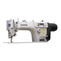
Checking the clearance between the rotary hook
and bobbin case holder position bracket
Check that the clearance between the rotary hook (6) and
the bobbin case holder position bracket (7) is enough to
allow the thread being used to pass through smoothly.
The clearance should be 0.4 - 0.7 mm for light and
medium-weight materials, and 0.6 - 0.9 for heavy-weight
materials.
0928M
0929M