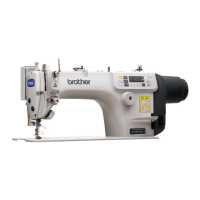
SL-710A
INDEX
1. SPECIFICATIONS....................................
1
2. OPTIONAL PARTS..................................
3
3. NOTES ON HANDLING ..........................
4
4. MECHANICAL DESCRIPTIONS .............
5
4-1. Upper shaft and needle bar mechanism .......5
4-2. Lower shaft and rotary hook mechanism ......5
4-3. Feed mechanism...........................................6
4-4. Quick reverse mechanism.............................7
4-5. Lubrication mechanism
(Thread take-up lever and rotary hook)........8
4-6. Thread trimmer mechanism ........................10
4-6-1. Thread trimmer operation..........................10
4-6-2. Upper and lower thread trimming..............12
4-7. Tension release mechanism ........................13
4-8. Thread wiper mechanism.............................14
4-9. Presser foot lifter mechanism
(-9[][], Option) (built into machine head)......14
4-10. Lower thread detector mechanism.............15
5. DISASSEMBLY
...............................................16
5-1. Bed cover and safety switch........................16
5-2. Connectors ..................................................17
5-3. Solenoid-type presser lifter
(-9[][], Option) ..............................................17
5-4. Lower thread detector
(-31[], -41[], -91[], Option)............................17
5-5. Covers and operation panel ........................18
5-6. Tension release wire, ground wire and
thread trimmer solenoid...............................19
5-7. Wick holder and oil tube
(Thread take-up lever).................................20
5-8. Oil tank, Bed under cover and sub tank ......20
5-9. Quick reverse solenoid................................21
5-10. Needle, presser hoot and
reverse actuator assy..................................22
5-11. Thread tension mechanism........................22
5-12. Needle plate and Feed dog .......................22
5-13. Bobbin case, rotary hook and
thread trimming mechanism........................23
5-14. Feed bar mechanism..................................23
5-15. Feed rocker shaft .......................................23
5-16. Presser foot mechanism.............................24
5-17.Knee lifter lever mechanism........................24
5-18. Needle bar and thread take-up mechanism25
5-19. Pulley and motor ........................................25
5-20. Timing belt..................................................26
5-21. Spring and feed regulator...........................26
5-22. Lower shaft, lower shaft gear and
feed regulator set.........................................27
5-23. Plunger, rotary hook shaft, gear
and thread trimmer cam ..............................27
5-24. Stitch length dial .........................................28
5-25. Reverse stitching lever and feed regulator.28
6. ASSEMBLY
.......................................................29
6-1. Stitch length dial, reverse stitching lever
and feed regulator mechanism....................29
6-2. Rotary hook shaft, thread trimmer
cam and gear...............................................31
6-3. Plunger ........................................................31
6-4. Lower shaft, lower shaft gear
and feed regulator set..................................32
6-5. Timing belt, motor and pulley ......................34
6-6. Knee lifter lever mechanism........................36
6-7. Needle bar and thread take-up mechanism 36
6-8. Presser foot mechanism..............................39
6-9. Feed rocker shaft ........................................40
6-10.Spring ..........................................................40
6-11.Feed bar mechanism...................................41
6-12.Sub tank, wick holder and wick ...................42
6-13.Thread tension mechanism.........................43
6-14.Oil (Feed rocker shaft).................................44
6-15.Thread trimming mechanism.......................44
6-15-1. Installing the thread trimmer cam lever 44
6-15-2. Adjusting the needle and
feed mechanism timing................................45
6-15-3. Installing the movable knife and
fixed knife.....................................................46
6-15-4. Adjusting the thread trimming timing....47
6-16.Rotary hook and bobbin case
holder position bracket ................................48
6-17.Ruler plate and needle plate .......................49
6-18.Reverse actuator assembly
and presser hoot..........................................49
6-18-1. Adjusting the presser foot height.............50
6-18-2. Adjusting the thread guide height............50
6-18-3. Adjusting the tension spring
vertical position............................................50
6-18-4. Adjusting the thread tension bracket
forward/back position...................................50
6-19.Tension release wire ...................................51
6-20.Quick reverse solenoid................................52
6-21.Bed under cover (Gear box)........................53
6-22.Oil tank ........................................................54
6-23.Tension release wire ...................................55
6-24.Ground wire.................................................55
6-25.Operation panel...........................................55
6-26.Face plate and thread take-up cover...........56
6-27.Safety switch ...............................................57
6-28.Arm cover, rear cover and
bobbin winder tension assembly .................57
6-29.Other devices ..............................................57
6-30.Connectors ..................................................58
6-31.Lubrication...................................................59
6-32.Bed cover and knee lifter lever....................60
6-33.Test operation..............................................61
6-34.Adjusting the safety switch position.............62