6. ASSEMBLY
SL-710A
36
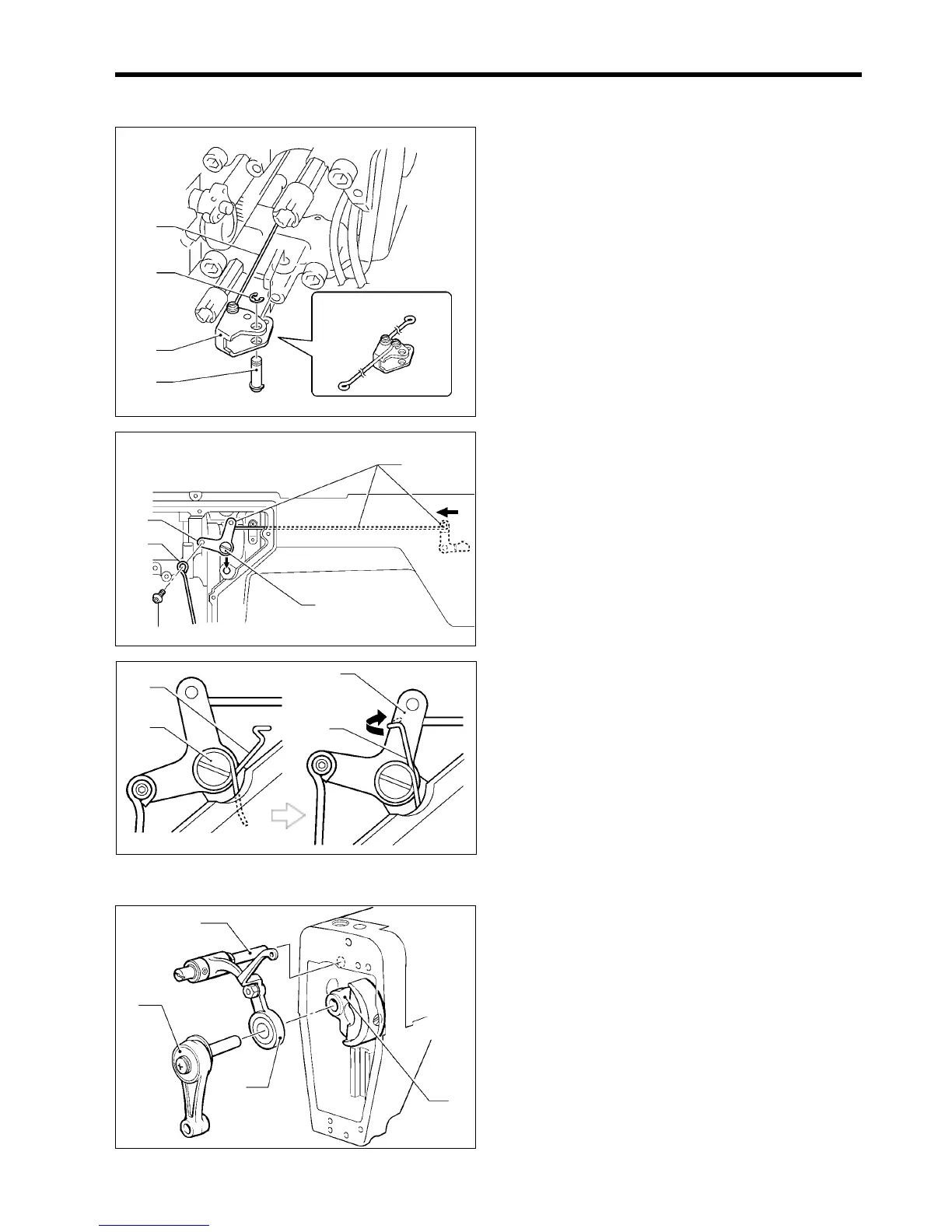
6-6. Knee lifter lever mechanism
1. Move the knee lifter connecting rod D (1) as far to the
left as possible, and then insert knee lifter lever D (2)
into the arm bed.
2. Insert lever shaft D (3) into knee lifter lever D (2) from
underneath, and then attach retaining ring E (4).
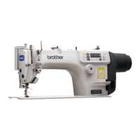
3. Insert presser bar lifter lever assembly (5) from the
side of the machine head, and then install the knee
lifter lever (7) to the arm bed with the shoulder screw
(6) as shown in the illustration.
4. Install knee lifter connecting rod D (1) to the knee lifter
lever (7) with the shoulder screw (8).
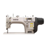
5. Install the spring (9) to the shoulder screw (6) so that it
faces as shown in the illustration.
6. Hook the bent end of the spring (9) onto the knee lifter
lever (7).
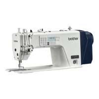
6-7. Needle bar and thread take-up mechanism
1. Insert the thread take-up support shaft (1) into the
machine head as shown in the illustration.
2. Insert the crank (2) into the thread take-up assembly
(3), and then insert it into the upper shaft assembly (4)
as far as it will go.
1729M
(1)
(4)
(2)
(3)
<-3[][],-4[][]>
(7)
1730M
(1)
(6)
(5)
(8)
1732M
1731M
(9)
(6)
(7)
(9)
1733M
(1)
(2)
(4)
(3)