6. ASSEMBLY
SL-710A
37
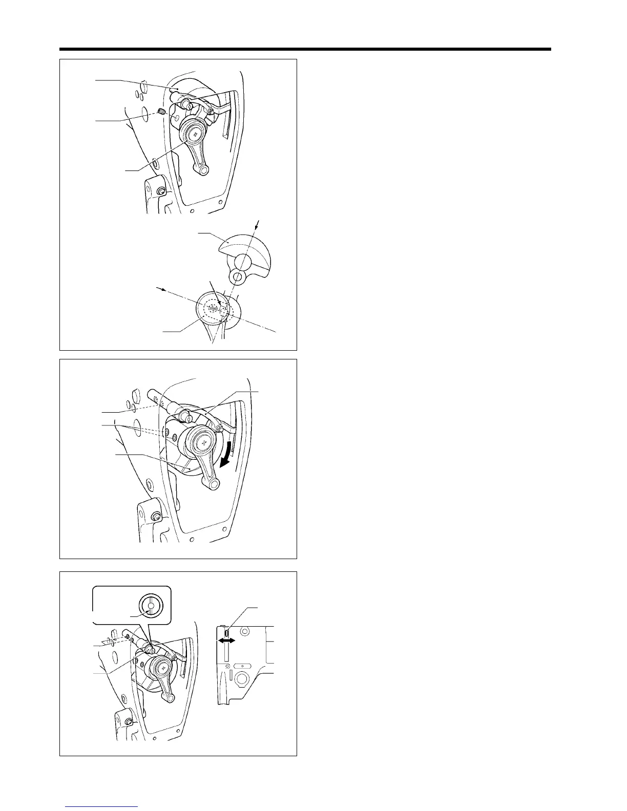
3. Set the thread take-up crank (5) so that line (A) is at a
right angle to line (B) on the crank (2), and then while
pushing the crank (2), tighten the set screw (6).
(At this time, align the screw stop of the crank (2) with
the set screw (6) when tightening it.)
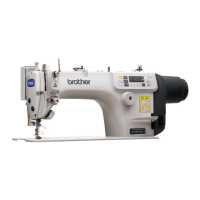
4. Turn the pulley to rotate the thread take-up crank (5),
and then tighten the two set screws (6).
5. Turn the pulley back and forth two or three times by
about 90°. (The upper shaft will turn and the thread
take-up assembly (3) will move into position.)
After doing this, provisionally tighten the set screw (7)
on the face plate.
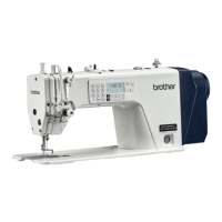
6. Gently move the thread take-up lever (8) to the left and
right and check that there is a small amount of
sideways play in the thread take-up lever (8).
7. Set the thread take-up support shaft (1) so that the
positioning notch is vertical, and then tighten the two
set screws (7).
1736M
(7)
(6)
(5)
(3)
(8)
Positioning notch
(7)
(1)
1737M
1734M
(5)
(6)
(2)
(5)
(2)
(B)
(A)
Approx. 90°
1