2
Design and Function
8/79 ekr CON 600 net – Process Data Exchange via Profibus
2.2 Profibus Interface Module
2.2.1 Arrangement
The ekrCON600net controller is connected to the customer con-
trol system via a Profibus interface module, which is factory integ-
rated in the controller housing.
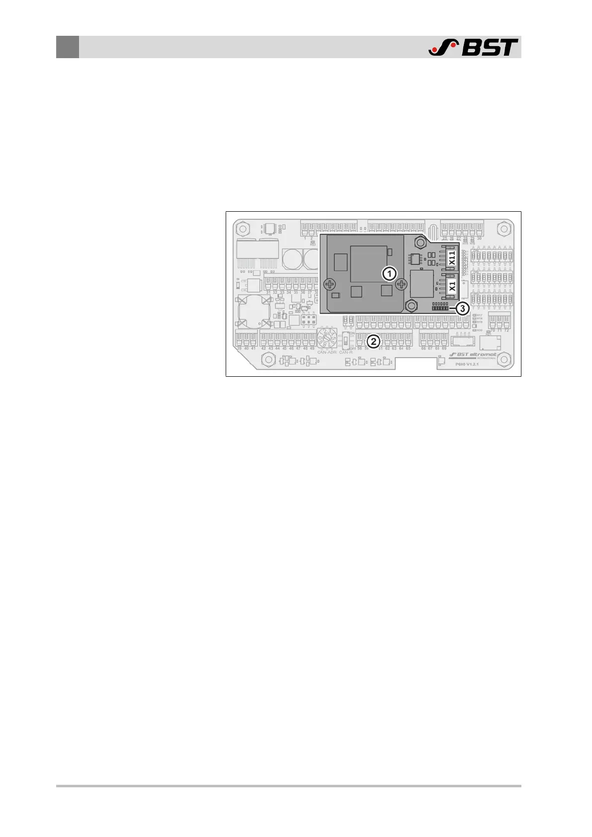
The following illustration shows the arrangement of the Profibus
interface module on the processor board of the controller.
Fig.2: Arrangement of the interface module on the processor board of the controller
①
Profibus interface module
②
Processor board
③
Status LEDs
On the Profibus interface module there are the two network
connections X1 and X11 as well as six status LEDs indicating the
operating status of the network connection and of the interface
module (see Status LEDs on the Profibus Interface Module, page
10).

 Loading...


