Visual-ICE™ Cryoablation System
8-3
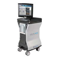
Table 8-1. Cable Lengths
Cable Length
Power Cable 4.6 m (15 ft)
Ethernet Cable 3 m (10 ft)
Gas Tubing
(connected to needles)
2.5 m (8 ft)
Gas Supply Lines
(connected to argon and
helium gas cylinders)
Available lengths:
5 m (16 ft), 8 m (26 ft)
NOTE: The Gas Supply Lines are available in more than one length to accommodate procedure room
variations.
WARNING. Use of cables other than those specied, with the exception of those sold by
Galil Medical for use as replacement parts for internal components, may result in increased
emissions or decreased immunity of the Visual-ICE Cryoablation System.
WARNING. The Visual-ICE Cryoablation System should not be used adjacent to or stacked
with other equipment. If adjacent or stacked use is necessary, the Visual-ICE System should
be observed to verify normal operation.
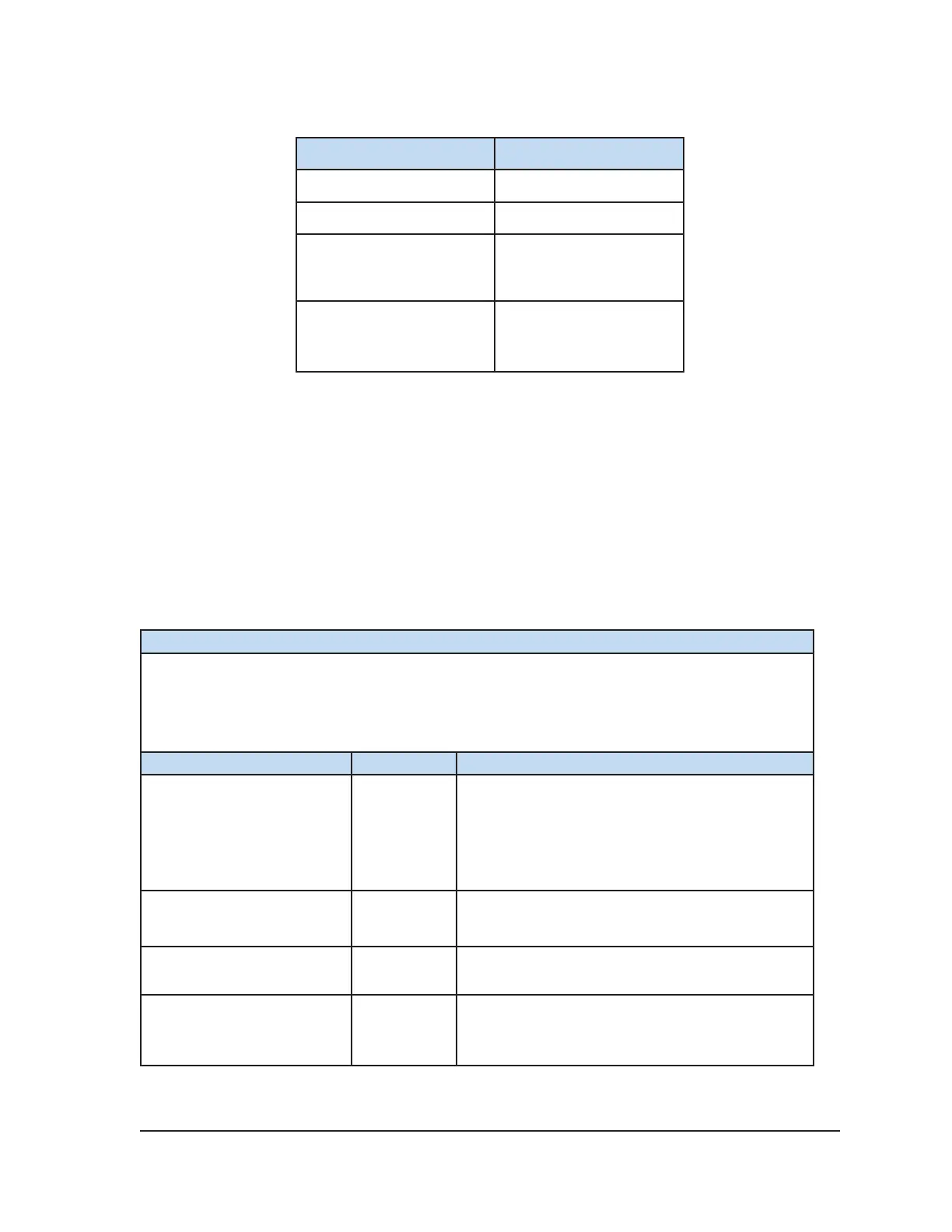
Table 8-2. Electromagnetic Emissions
Guidance and manufacturer’s declaration – electromagnetic emissions
The Visual-ICE Cryoablation System is intended for use in the electromagnetic environment
specified below. The customer or the user of the Visual-ICE System should assure that it is used in
such an environment.
Emissions test Compliance Electromagnetic environment – guidance
RF emissions CISPR 11 Group 1
The Visual-ICE System uses RF energy only for its
internal function. Therefore, its RF emissions are very
low and are not likely to cause any interference in
nearby electronic equipment.
RF emissions CISPR 11 Class B
Harmonic emissions, IEC
61000-3-2
Class A
Voltage uctuations/ icker
emissions, IEC 61000-3-3
Complies