Visual-ICE™ Cryoablation System
4-7
6. Route the helium gas supply line through the supply line clip on the Console.
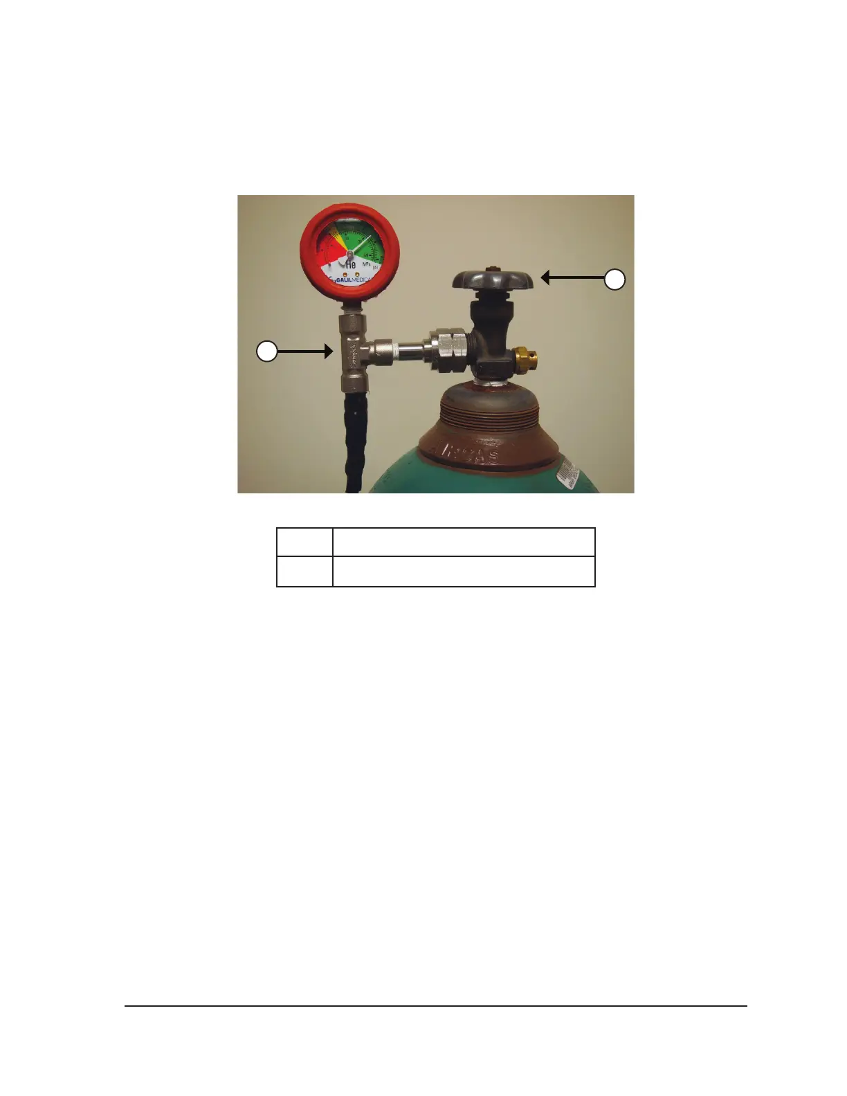
7. Connect the helium high-pressure gas supply line to the helium cylinder by securing the gauge
assembly adapter onto the cylinder connection (Figure 4-2).
NOTE: Gas cylinder connections have left-handed threads.
2
1
Figure 4-2. Gas Cylinder Set-up
1 Gauge assembly adapter
2 Cylinder valve
8. Carefully turn the cylinder valve on the helium gas cylinder counter-clockwise for one quarter
turn. Ensure that the pressure reading on the gauge responds immediately. Turn the cylinder
valve further counter-clockwise (approximately one full turn) to fully open the gas cylinder so that
sucient gas ow is present.
9. Repeat the procedure outlined in Steps 4 through 8 to connect the argon gas cylinder to the
Visual-ICE System, using the argon gas supply line.
If no argon pressure is displayed on the system pressure gauge, ensure the Argon Shuto Valve
is in the GAS ON position.
OPTIONAL:
• The EZ-Connect2 Dual Cylinder Adapter connects two cylinders of argon gas to the
Visual-ICE System to support a cryoablation procedure. A four-way adapter assembly with
argon pressure gauge connects a gas supply line, the primary gas cylinder, and an auxiliary
gas supply line.
• If using the optional EZ-Connect2 Adapter, connect the gas supply line with four-way
pressure gauge adapter assembly to the primary argon cylinder by securing the gauge
assembly adapter onto the cylinder connection.
• Connect the end of the gas supply line to the argon inlet of the Visual-ICE System using the
quick-connect connector.