4-8 User Manual
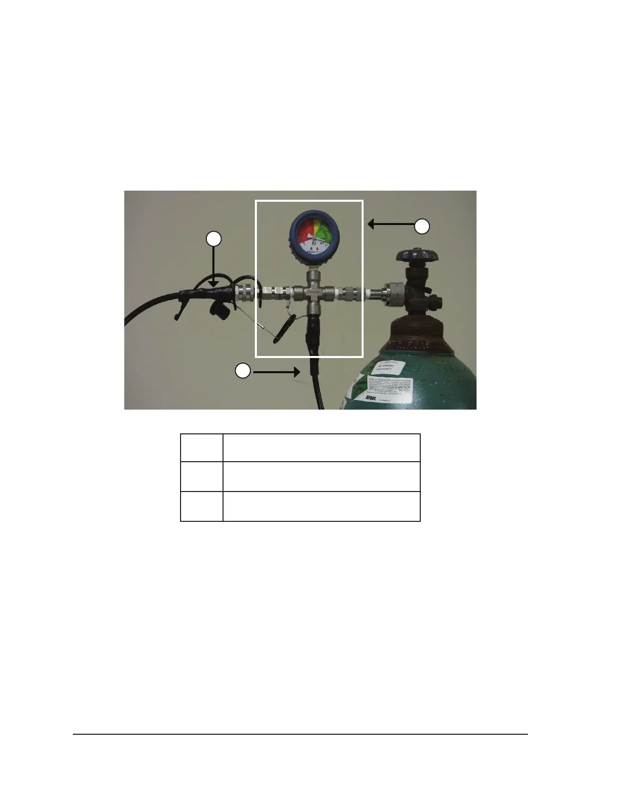
• Connect the auxiliary gas supply line to the four-way adapter assembly using the quick-
connect connector located on the end of the auxiliary gas supply line.
• Connect the opposite end of the auxiliary gas supply line to the second argon cylinder by
securing the end of the auxiliary line to the cylinder connection.
• Open the primary cylinder valve rst and use this cylinder until depleted. Do not open the
cylinder valve on the second cylinder until the initial cylinder has been depleted.
• Reference Section 4.5 for instructions on changing the gas cylinder during a procedure, if the
second cylinder is also depleted during the procedure.
2
3
1
Figure 4-3. EZ-Connect2 Dual Cylinder Adapter
1 Auxiliary Gas Supply Line
2
Four-way Adapter Assembly with
Pressure Gauge
3 Gas Supply Line
CAUTION. Before beginning the cryoablation procedure, ensure availability of sucient gas to
conduct the planned cryoablation procedure (reference Section 8.5 for gas purity requirements).
10. Ensure the Gas Indicator (Screen 3-4) displays the minimum working pressure before initiating a
procedure (Table 4-2). The Gas Indicator should indicate the pressure to be in the green range.
If the system detects that the pressure reading for either gas cylinder is less than 50 psi, a
message displays on the Navigation Tool Bar (Screen 4-8). Connect the gas cylinders to the
Visual-ICE System.


 To Next Page