iv User Manual
List of Figures
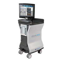
Figure2-1.Visual-ICECryoablationSystemFrontView 2-2
Figure2-2.Visual-ICECryoablationSystemRearView 2-3
Figure 2-3. Monitor Storage Compartment 2-4
Figure2-4.Visual-ICECryoablationSystemNeedleConnectionPanel 2-6
Figure2-5.Visual-ICECryoablationSystemNeedleChannel 2-6
Figure4-1.Visual-ICESystemGasConnections 4-6
Figure 4-2. Gas Cylinder Set-up 4-7
Figure 4-3. EZ-Connect2 Dual Cylinder Adapter 4-8
Figure 4-4. Locking Needle into Channel 4-11
Figure 4-5. MTS Connection 4-14