Modules and their functions
5
Logamatic 4323 - Subject to technical modifications. 13
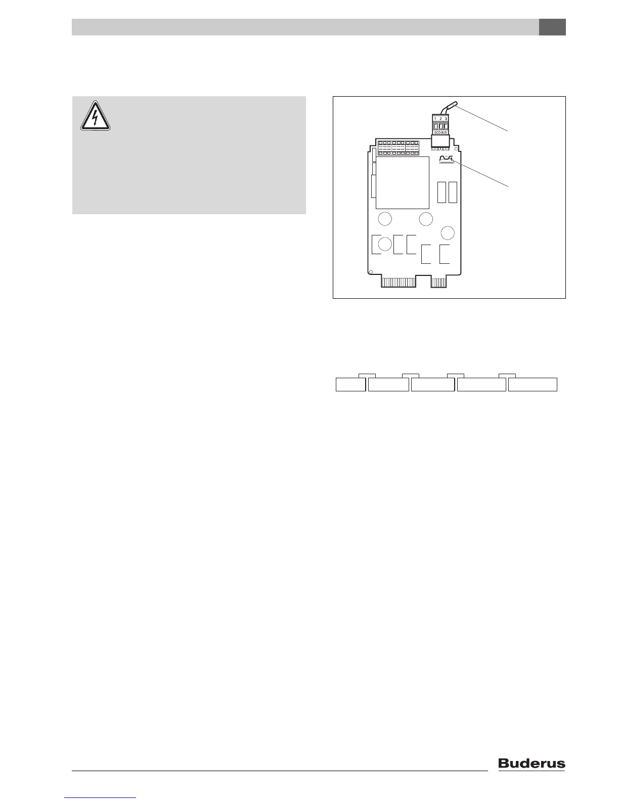
5.2 NM482 power supply module
Terminator when networking several control units
To ensure fault free data transmission between several
control units, fit a terminator to the two control units
which are furthest apart.
The terminator is fitted to the component side of the
NM482 power supply module, and is switched on by
the
gravity switch (Æ Fig. 6, [2]).
The factory setting is:
Gravity switch S1 open = terminator not fitted.
Fig. 6 NM482 power supply module
1 ECOCAN-BUS
2 Gravity switch S1 (for terminator) factory setting: open
WARNING!
RISK TO LIFE
from electric shock!
z Ensure that all electrical work is only
carried out by an authorised electrician.
z Before opening the control unit: Isolate
all poles of the mains power supply and
secure against unintentional
reconnection.

 Loading...


