Fault
20
Logamatic 4323 - Subject to technical modifications.
105
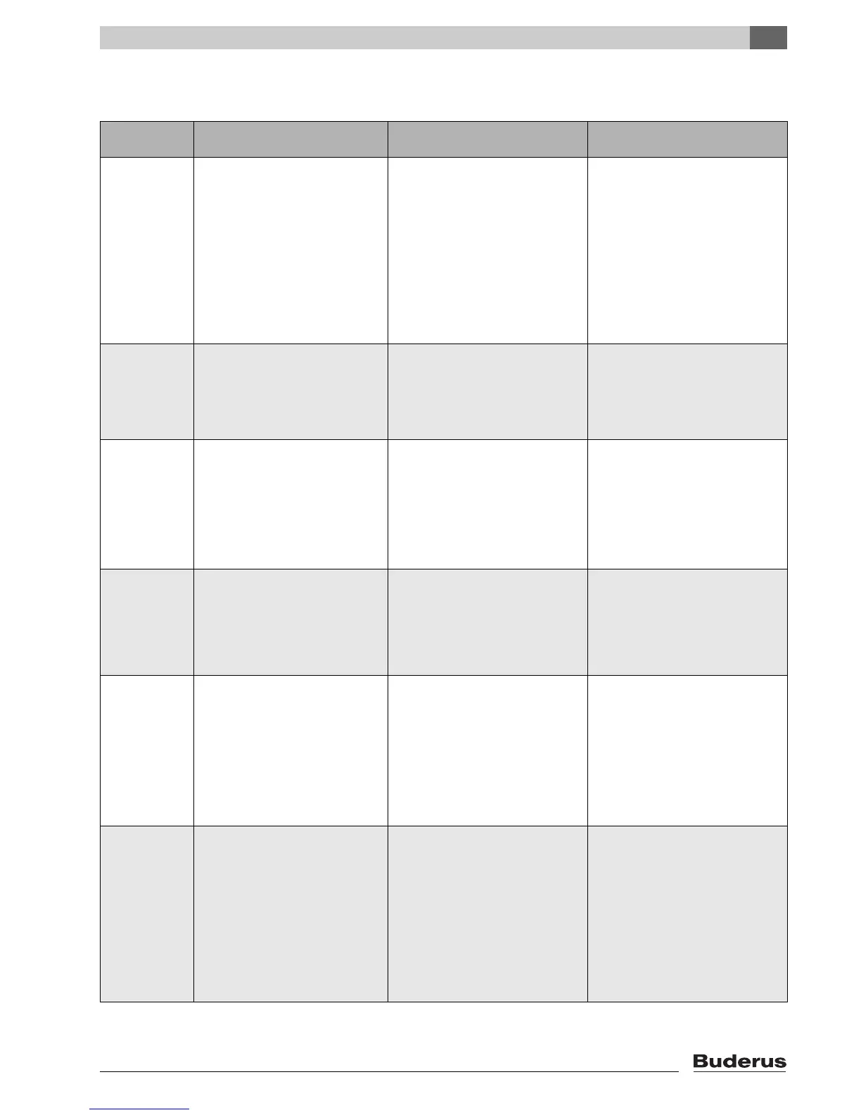
20 Fault
Fault Effect on control
characteristics
Possible causes of the fault Remedy
Outs. temp.
sensor
– The minimum outside
temperature is applied instead of
the actual outside temperature.
– The outside temperature sensor is
either faulty, not connected or is not
plugged into the control unit at the
control unit with address 1, or is
contacted at the wrong module.
– Checks of the outside temperature
sensor.
– Check whether the outside
temperature sensor is connected to
the control unit with address 1 (for
information regarding the position
of the outside temperature sensor
see Æ Chapter 5.1).
– Communication to control unit with
address 1 is interrupted.
– Check communication with
address 1.
– Central module or control unit
is faulty.
– Replace outside temperature
sensor or central module.
Flow sensor x
– The mixer is no longer being
controlled.
– Sensor is faulty or not connected. – Check sensor connection.
– An actuator (mixer) was
inadvertently selected for the
heating circuit.
– If the heating circuit is to be
operated without an actuator,
enter "No" under actuator in the
appropriate menu of the MEC2
(Æ Chapter 11.20).
DHW sensor
– DHW is no longer heated. – Sensor is faulty or not connected. – Check sensor connection.
– Check sensor connection on the
DHW cylinder.
– DHW was inadvertently selected. – Deselect DHW in the MEC2 under
parameter DHW data, if DHW
heating is no longer required
(Æ Chapter 12).
– Module or control unit faulty. – Replace sensor or module.
DHW stays
cold
– DHW is no longer heated. Current
DHW temperature is below 40°C.
– Primary pump faulty.
– FM441 function module faulty.
– More DHW is removed than newly
heated.
– Check whether the thermostat or
the switch is set to "AUT".
– Check function of sensor and
primary pump.
– Replace FM441 module.
– Check sensor connection on the
DHW cylinder.
DHW warning
– There is a constant attempt to fill
the DHW cylinder.
– DHW priority is switched off after
this fault message is displayed.
– Constant drawing or system leak. – Stop the any leaks.
– Switch not set to "AUT". – Check whether the switch is set to
"AUT".
– Sensor faulty or not connected.
Sensor incorrectly mounted.
– Check sensor connection and
values.
– Primary pump incorrectly
connected or faulty.
– Check the primary pump function,
e.g. with a relay test
(Æ Chapter 16).
– Module or control unit faulty. – Replace sensor or module.
Thermal
disinfection
– Thermal disinfection was
terminated.
– Too much water drawn during
thermal disinfection.
– Boiler output is temporarily
insufficient due to heat drawn by
other consumers (e.g. heating
circuits).
– Select a time for thermal
disinfection when there is no other
demand for heat.
– Sensor is faulty or not connected,
or primary pump is faulty.
– Check sensor and primary pump
function, and replace if required
(Æ Chapter 16 and 25).
– Module or control unit faulty. – If necessary, replace module or
control unit.
Tab. 4 Fault table

 Loading...


