EasyManuals Logo

Buell 2006LIGHTNING MODELS User Manual

Buell 2006LIGHTNING MODELS
638 pages
To Next Page IconTo Next Page
To Previous Page IconTo Previous Page
Page #262 background imageLoading...
Page #262 background image
3-28 2006 Buell Lightning: Engine
HOME
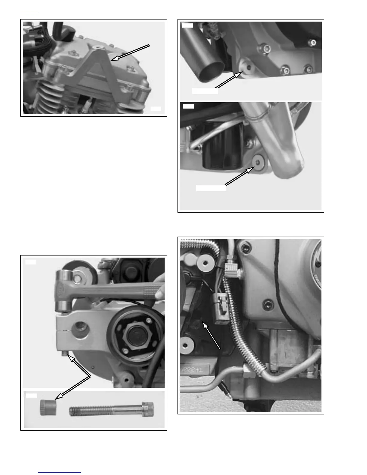
40. Once engine has been removed from vehicle finish
removing the following items as required:
a. Shifter assembly.
b. See Figure 3-27. Center tie bar mount.
c. See Figure 3-28. Swingarm pivot shaft pinch bolt
threaded insert.
d. See Figure 3-29. Aluminum bushings from front
exhaust mount.
e. Timer cover.
f. See Figure 3-30. Wire guard located under the
sprocket cover.
Figure 3-27. Center Tie Bar Mount
Figure 3-28. Removing Threaded Insert
8725
8724
8729
Figure 3-29. Front Exhaust Mount Bushings (2 piece)
Figure 3-30. Wire Guard
Left Side
Right Side
8718
8727

Table of Contents

Questions and Answers:

Question and Answer IconNeed help?

Do you have a question about the Buell 2006LIGHTNING MODELS and is the answer not in the manual?

Buell 2006LIGHTNING MODELS Specifications

General IconGeneral
BrandBuell
Model2006LIGHTNING MODELS
CategoryMotorcycle
LanguageEnglish

Related product manuals