2006 Buell Lightning: Engine 3-59
HOME
CYLINDER HEAD INSTALLATION
NOTE
● Short head bolts will be installed in the 1 and 2 positions,
and long head bolts in the 3 and 4 positions.
● Thoroughly clean and lubricate the threads of the cylin-
der head screws before installation. Friction caused by
dirt and grime will result in a false torque indication.
1. Thoroughly clean and dry the gasket surfaces of cylin-
ders and cylinder heads.
2. Install new o-rings over two ring dowels at the top of the
cylinder. Apply a very thin film of clean H-D 20W50
engine oil to o-rings before installation.
NOTE
To ensure proper head gasket alignment, install new o-rings
over cylinder ring dowels before installing the head gasket.
Improper head gasket alignment will cause leaks.
3. Install a new head gasket to cylinder.
4. Carefully lower cylinder head over studs and position on
dowels. Use great care so as not to disturb head gasket.
5. Lightly coat the threads and bottom face of the cylinder
head bolts with clean H-D 20W50 engine oil. Wipe off
any excess oil.
NOTE
The procedure for tightening the head screws is critical to
proper distribution of pressure over gasket area. It prevents
gasket leaks, stud failure, and head and cylinder distortion.
Always tighten in sequence shown.
6. Start the cylinder head screws onto the cylinder studs,
two short bolts on the left side of the engine, two long
bolts on the right.
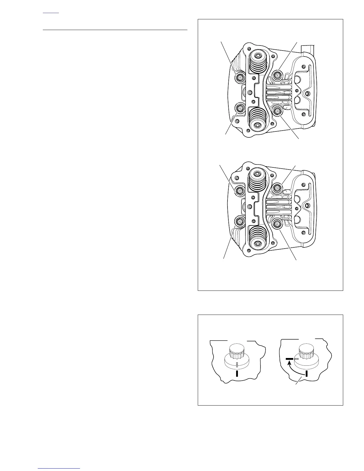
7. See Figure 3-82. For each cylinder head, start with
screw numbered one, as shown. In increasing numerical
sequence (i.e. – 1, 2, 3 and 4):
a. Tighten bolts to 96-120 in-lbs (11-14 Nm).
b. Tighten bolts to 13-15 ft-lbs (18-20 Nm).
c. Loosen all screws.
8. After screws are loosened from initial torque, tighten
head screws in three stages. Tighten fasteners in
increasing numerical sequence (i.e. – 1, 2, 3 and 4).
a. Tighten each screw to 96-120 in-lbs (11-14 Nm).
b. Tighten each screw to 13-15 ft-lbs (18-20 Nm).
c. See Figure 3-83. Mark cylinder head and head
screw shoulder with a line as shown (View A).
d. Turn all bolts an additional 85 -95 .°°
Figure 3-82. Head Screw Loosening/Tightening Sequence
Figure 3-83. Tightening Head Screws
Head Screw Loosening/Tightening Sequence
Rear Cylinder
Front Cylinder
3rd
2nd
1st
4th
x0128x3a
1st
2nd
3rd
4th
View
A
View
B
a0089x3x
Tighten head screws 1/4-turn in
the third stage of installation