2006 Buell Lightning: Drive/Transmission 6-53
HOME
TRANSMISSION SPROCKET 6.16
REMOVAL
NOTE
Use spacer and fastener from B-45659 to install sprocket
locking tool.
1. Loosen rear axle pinch fastener. See IDLER PULLEY
REMOVALs 6.6 DRIVE BELT SYSTEM.
2. Unthread axle approximately 15 threads to release ten-
sion from drive belt.
3. Remove front sprocket cover. See 2.33 SPROCKET
COVER.
4. See Figure 6-100. Remove both bracket nuts with wash-
ers (5) attaching idler pulley bracket (4) to studs (3).
5. Slide idler pulley assembly off studs.
6. Inspect pulley by spinning wheel (1) and checking for
excessive wheel bearing wear.
7. If pulley wheel needs replacement, remove fastener (6)
and nut (2) from idler pulley bracket (4) and discard.
Replace with new pulley wheel (1).
NOTE
The pulley wheel bearings can not be replaced separately. A
new pulley wheel must be installed.
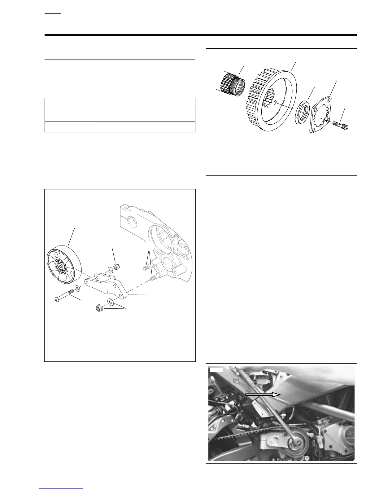
8. See Figure 6-101. Place transmission in first gear.
Remove two socket head screws (1) and lockplate (2).
NOTES
● Transmission sprocket nut has left-hand threads. Turn
nut clockwise to loosen and remove from main drive gear
shaft.
● Use the P3/Blast SPROCKET HOLDING TOOL (Part No.
B-43982) with the spacer and fastener from the Firebolt
SPROCKET LOCKING TOOL (Part No. B-45659) to hold
the sprocket.
9. Place transmission in neutral. See Figure 6-102. Install
the P3/Blast SPROCKET HOLDING TOOL to hold the
sprocket.
10. Remove transmission sprocket nut (3) from main drive
gear (5) using MAINSHAFT LOCKNUT WRENCH (Part
No. HD-94660-37B or HD-46288) and a breaker bar.
11. Remove secondary drive belt from transmission
sprocket. Remove transmission sprocket (4) from main
drive gear (5).
PART NO. SPECIALTY TOOL
B-45659 Transmission sprocket locking tool
HD-94660-37B Mainshaft locknut wrench
Figure 6-100. Idler Pulley Assembly
b1106x6x
2
3
4
5
6
1. Wheel
2. Wheel nut
3. Stud (2)
4. Idler pulley bracket
5. Idler pulley bracket nut with washer (2)
6. Wheel fastener
1
Figure 6-101. Transmission Sprocket
Figure 6-102. Removing Transmission Sprocket Locknut
1. Socket head screw (2)
2. Lockplate
3. Transmission sprocket nut (left-hand threads)
4. Transmission sprocket
5. Main drive gear
1
2
3
4
5
d0117x6x