6-52 2006 Buell Lightning: Drive/Transmission
HOME
2. See Figure 6-98. Depress ratchet arms and insert shaft
assembly into the bushing in the left case half and
release. Ratchet arms should now be inside the end
plate of the shifter drum contacting the shifter drum pins.
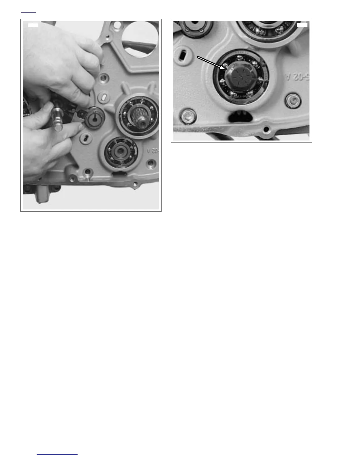
3. See Figure 6-99. Apply several drops of LOCTITE 262
(red) to last few threads of countershaft retaining screw.
Thread screw into end of shaft.
4. Place transmission in gear and tighten screw (1) to 33-37
ft-lbs (44.8-50 Nm).
5. Install transmission sprocket. See 6.16 TRANSMISSION
SPROCKET.
6. Continue assembling engine. See appropriate sections
of 3.19 CRANKCASE and 3.6 CYLINDER HEAD/3.7
CYLINDER AND PISTON.
7. Install primary chain and engine sprocket, clutch assem-
bly and primary cover. See 6.5 PRIMARY CHAIN.
8. Install engine in chassis. See 3.5 ENGINE INSTALLA-
TION.
Figure 6-98. Installing Shifter Shaft Assembly
11403
Figure 6-99. Hex Fastener Countershaft Retainer
11340