2006 Buell Lightning: Fuel System 4-93
HOME
ELECTRONIC CONTROL MODULE 4.30
GENERAL
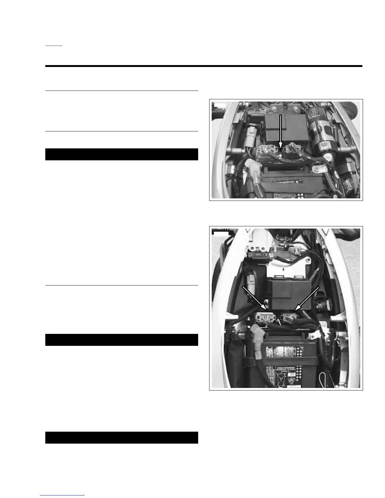
See Figure 4-69. The Electronic Control Module (ECM) is
located under the seat.
REMOVAL
1. Remove seat. See 2.43 SEAT.
1WARNING1WARNING
Disconnect negative (-) battery cable first. If positive (+)
cable should contact ground with negative (-) cable con-
nected, the resulting sparks can cause a battery explo-
sion, which could result in death or serious injury.
(00049a)
2. Disconnect and remove battery. See 1.4 BATTERY
MAINTENANCE.
3. Disconnect ECM black connector [10] and gray connec-
tor [11].
4.
For XB12 Models:
Remove the interactive exhaust con-
nector [164].
5. Remove the two fasteners to detach electronic control
module from bracket.
INSTALLATION
1. Align holes in ECM with those in electrical bracket. Install
two fasteners and tighten to 48-72
in-lbs
(5.4-8 Nm).
2. Attach ECM connectors [10] and [11].
3.
For XB12 Models:
Attach the interactive exhaust con-
nector [164].
1WARNING1WARNING
Connect positive (+) battery cable first. If positive (+)
cable should contact ground with negative (-) cable con-
nected, the resulting sparks can cause a battery explo-
sion, which could result in death or serious injury.
(00068a)
4. Install battery by threading positive cable (red) into
threaded hole first tightening to 72-96
in-lbs
(8-11 Nm).
See 1.4 BATTERY MAINTENANCE.
5. Connect negative battery cable.
6. Zero TPS. See 4.37 THROTTLE POSITION SENSOR.
1WARNING1WARNING
After installing seat, pull upward on front of seat to be
sure it is in locked position. While riding, a loose seat can
shift causing loss of control, which could result in death
or serious injury. (00070a)
7. Install seat. See 2.43 SEAT.
NOTE
If the ECM was replaced with a new component, it will be
necessary to recalibrate Throttle Position Sensor. Throttle
position sensor can only be calibrated using DIGITAL TECH-
NICIAN (Part No. HD-44750).
Figure 4-69. ECM (Typical)
Figure 4-70. ECM (XB12Ss)