2-60 2006 Buell Lightning: Chassis
HOME
SWINGARM AND BRACE 2.19
GENERAL
The swingarm also serves as the oil tank. For information on
the swingarm function as the oil tank, see 3.9 OIL HOSE
ROUTING AND OIL RESERVOIR.
The swingarm features a removable brace on the right side to
allow drive belt replacement. Sealed bearings eliminate the
need for preload adjustment.
REMOVAL
Brace
NOTE
Before removing swingarm brace, always relieve belt tension
first. Removing swingarm brace without releasing tension will
cause swingarm brace damage.
1. Remove right side rider footpeg mount. See 2.32 FOOT-
PEG, HEEL GUARD AND MOUNT.
2. See Figure 2-82. Loosen rear axle pinch fastener (2).
3. Loosen rear axle (1) approximately 15 rotations to allow
partial tension to be removed from rear drive system.
4. See Figure 2-85. Remove swingarm brace mounting fas-
teners (10).
5. Remove swingarm brace (11).
Figure 2-82. Rear Wheel Mounting, Right Side (XB12Ss)
11810
2
1. Axle
2. Pinch bolt fastener
1
Figure 2-83. Belt Guard and Rear Fender Assembly
(XB9SX, XB12S, XB12Scg)
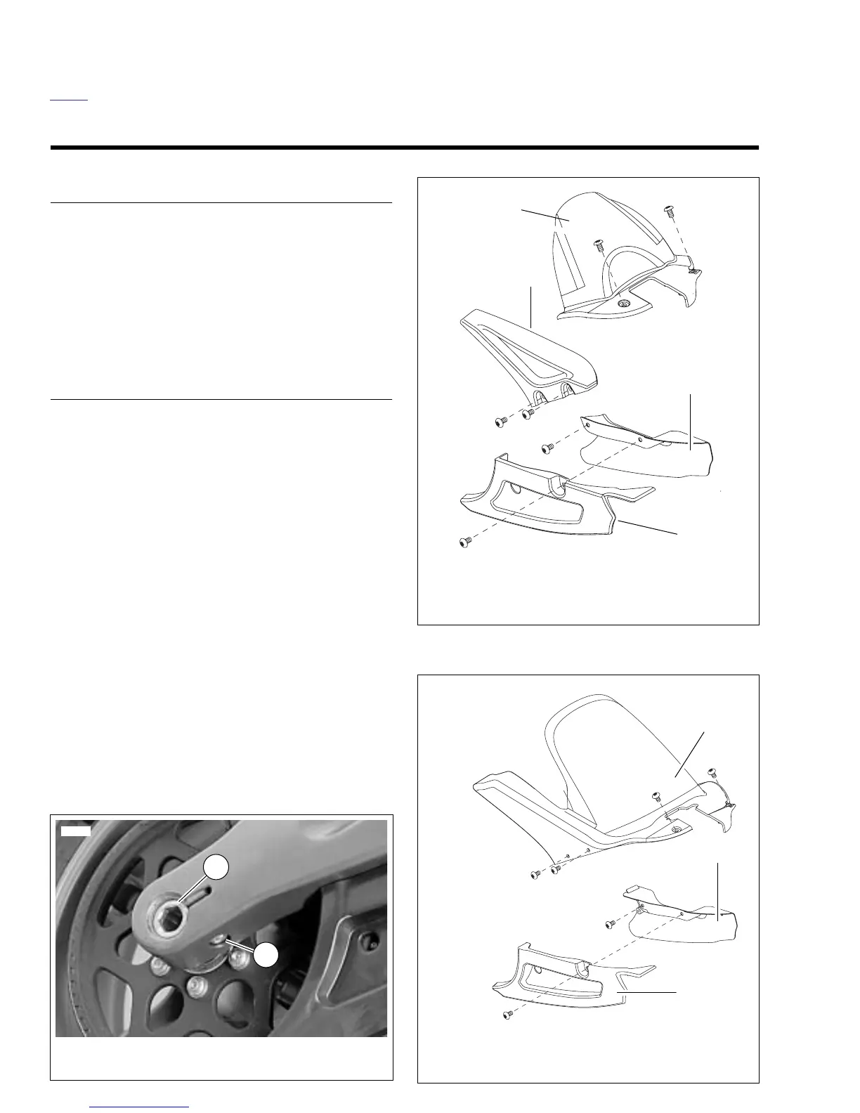
Figure 2-84. Belt Guard and Rear Fender Assembly
(XB12Ss)
b1251x1x
1. Fender
2. Upper belt guard
3. Stone guard
4. Lower belt guard
4
3
2
1
b1252x1x
1. Rear inner fender/belt guard
2. Stone guard
3. Lower belt guard
1
2
3