4-56 2006 Buell Lightning: Fuel System
HOME
TROUBLE CODE 15 4.19
GENERAL
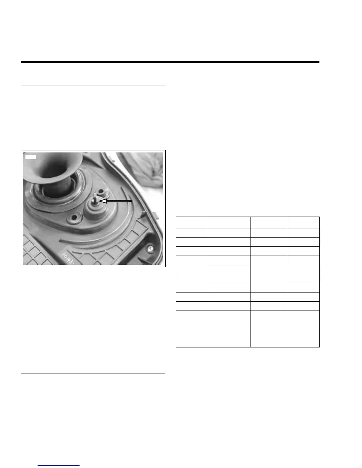
Intake Air Temperature Sensor
See Figure 4-40. The ECM supplies and monitors a signal at
Pin 10 of [11] to one side of the intake air temperature sensor
(IAT sensor). The other side of the IAT sensor is connected to
a common sensor ground, which is also connected to the
ECM (Pin 7 of [11]).
Refer to Ta ble 4-22. The IAT sensor is a thermistor device,
meaning that at a specific temperature, it will have a specific
resistance across its terminals. As this resistance varies, so
does the supplied voltage (Pin 10).
●
At high temperatures, the resistance of the sensor is very
low. This effectively lowers the signal voltage on Pin 10.
●
At low temperatures, the resistance is very high, allowing
the voltage to rise close to the supplied voltage of 5 volts.
The ECM monitors this voltage to compensate for various
operating conditions.
DIAGNOSTICS
Diagnostic Tips
An intermittent may be caused by a poor connection, rubbed
through wire insulation or a wire broken inside the insulation.
Check for the following conditions:
●
Poor connection.
Inspect ECM harness connector for
backed out terminals, improper mating, broken locks
improperly formed or damaged terminals, poor terminal-
to-wire connection and damaged harness.
●
Perform 4.7 WIGGLE TEST
to locate intermittents.
If
connections and harness check out OK, check intake air
temperature reading while moving related connectors
and wiring harness. If the failure is induced, the IAT sen-
sor display will change.
●
Shifted sensor.
The temperature-to-resistance values
table may be used to test the IAT sensor at various tem-
perature levels in order to evaluate the possibility of a
shifted (out-of-calibration) sensor which may result in
driveability problems.
Diagnostic Notes
The reference numbers below correlate with the circled num-
bers on the Code 15 flow charts.
1. Connect BREAKOUT BOX (Part No. HD-42682) to EFI
harness
only
(leave ECM disconnected). See 4.6 BREA-
KOUT BOX.
2. Use HARNESS CONNECTOR TEST KIT (Part No. HD-
41404), gray socket probes and patch cord.
3. Use HARNESS CONNECTOR TEST KIT (Part No. HD-
41404), gray pin probe and patch cord.
NOTE
All voltage and resistance values are approximate (+/- 20%).
Intake air temperature sensor is measured between Terminal
10 of [11] and system ground (Terminals 2 and 11 of [10]).
Figure 4-40. IAT Sensor
8380
Table 4-22. Intake Air Temperature
Sensor Specifications
VOLTS RESISTANCE TEMP °C TEMP °F
0.49 1086 125 257
0.68 1561 113 235
0.86 2077 100 212
1.13 2920 90 194
1.40 3889 80 176
2.25 8149 60 140
3.09 16,178 40 104
3.52 23,670 30 86
3.94 37,170 20 68
4.24 55,359 10 50
4.53 96,383 0 32
4.68 146,250 -10 14
4.83 284,118 -20 -4