7-66 2006 Buell Lightning: Electrical
HOME
MAIN WIRE HARNESS 7.24
GENERAL
The main wire harness runs from the front of the motorcycle
to the tail section.
Always replace plastic tree fasteners when replacing main
wire harness. Remove tree fasteners carefully, do not leave
any of fastener in frame.
REMOVAL
NOTES
● To ensure correct installation, make note of wire routing
and cable strap locations before removing main wire har-
ness.
● Main wire harness is removed from rear of vehicle
through fan section of frame.
1. Remove seat. See 2.43 SEAT.
2. Remove air cleaner cover. See 4.44 AIR CLEANER
ASSEMBLY.
3. Remove sprocket cover. See 2.33 SPROCKET COVER.
1WARNING1WARNING
Disconnect negative (-) battery cable first. If positive (+)
cable should contact ground with negative (-) cable con-
nected, the resulting sparks can cause a battery explo-
sion, which could result in death or serious injury.
(00049a)
4. Unthread fastener and remove battery negative cable
(black) from battery negative (-) terminal.
5. Pull back terminal cover boot on battery positive cable
(red).
6. Unthread fastener and remove battery positive cable
from battery positive (+) terminal.
7. Remove battery.
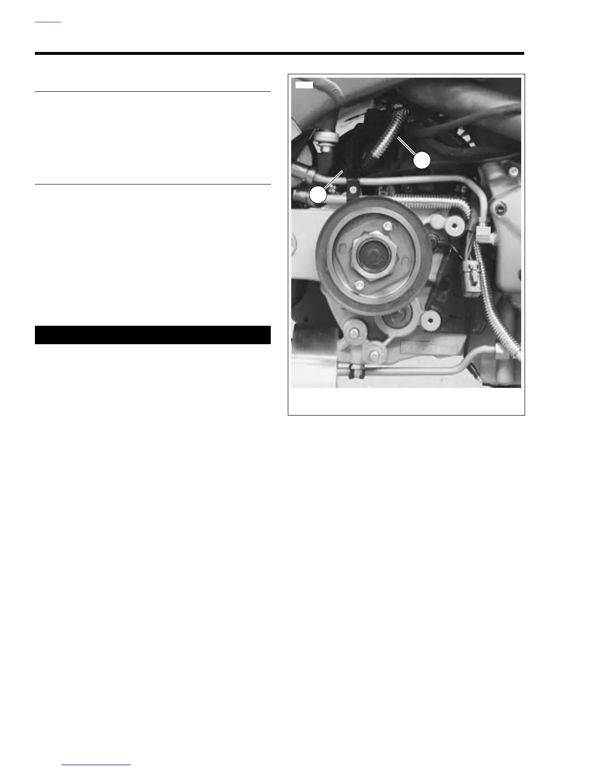
8. See Figure 7-86. Disconnect positive battery cable from
starter.
9. See Figure 7-87. Disconnect:
● Wire harness ground [GRD 2].
● Rear brake light switch connector [121].
● ECM connectors [10] and [11].
(ECM connector [164] on 1200 models)
● BAS (bank angle sensor) connector [134].
● Right turn signal connector [18].
● Left turn signal connector [19].
● License plate lamp connector [45].
● Tail light connectors [93].
● Ground terminals on right side tail section [GRD 1] &
[GRD 3].
● See Figure 7-87. Interactive exhaust connector
[165B], (under main wiring harness) (1200 models
only)
10. Remove fuse block and relay center from support
bracket.
11. Remove the rear shock absorber assembly and reser-
voir. See 2.22 REAR SHOCK ABSORBER.
12. Remove fan. See 4.38 COOLING FAN.
Figure 7-86. Positive Battery Cable
8742
1. Protective boot, positive battery cable
2. Positive battery cable
1
2