7-64 2006 Buell Lightning: Electrical
HOME
NEUTRAL INDICATOR SWITCH 7.22
GENERAL
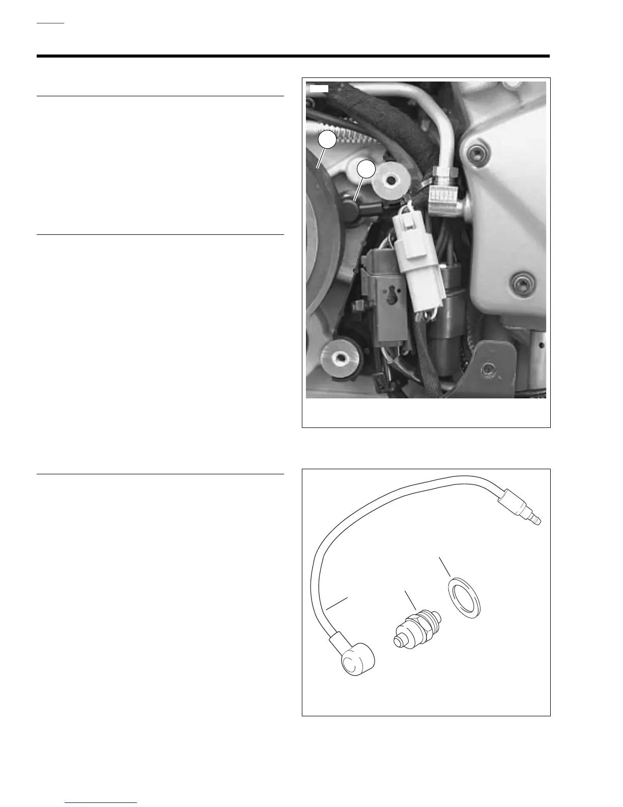
See Figure 7-82. The neutral indicator switch (2) is threaded
into the transmission portion of the right crankcase half. It is
immediately forward of the transmission sprocket (1). The
sprocket cover must be removed to test the switch.
A pin on the shifter drum contacts the neutral indicator switch
plunger, completing the neutral indicator circuit. The switch is
not repairable. Replace the switch if it malfunctions.
TESTING
1. Remove sprocket cover. See 2.33 SPROCKET COVER.
2. See Figure 7-82. Disconnect wire lead from neutral indi-
cator switch (2).
3. Turn ignition key switch to ON. Touch the neutral indica-
tor wire lead to a suitable ground.
a. If indicator lamp lights, then problem is at indicator
switch. Replace switch.
b. If indicator lamp does not light, then problem is else-
where in circuit. Check for loose connections,
burned out indicator lamps or faulty wiring.
c. After testing and repair, connect wire lead to indica-
tor switch.
4. Install sprocket cover. See 2.33 SPROCKET COVER.
REMOVAL/INSTALLATION
1. Verify that the ignition key switch is turned to OFF.
2. Remove sprocket cover. See 2.33 SPROCKET COVER.
NOTE
If replacing neutral indicator switch wiring, see 7.26
SPROCKET COVER WIRING for correct wire routing.
3. See Figure 7-83. Remove wire lead (1) from neutral indi-
cator switch (2).
4. Remove neutral indicator switch and washer (3).
5. Install new neutral indicator switch.
a. Apply a light coating of LOCTITE 243 (blue) to new
neutral indicator switch (2) threads.
b. Install washer (3) over neutral indicator switch (2)
threads.
c. Install switch in crankcase. Tighten switch to 36-60
in-lbs (4-6.8 Nm).
d. Connect wire lead (1) to switch.
6. Install sprocket cover. See 2.33 SPROCKET COVER.
Figure 7-82. Neutral Indicator Switch Location
Figure 7-83. Neutral Indicator Switch
11815
1. Transmission sprocket
2. Neutral indicator switch
2
1
1. Neutral indicator switch wire lead
2. Neutral indicator switch
3. Washer
1
2
3
b1029x8x