2006 Buell Lightning: Engine 3-57
HOME
7. See Figure 3-78. Coat the sleeve with oil and place a
new seal and lower collar assembly over the valve stem
and onto valve guide.
NOTES
● See Figure 3-77. The valve seal is now incorporated into
the lower collar and is installed by hand. NO SPECIAL
TOOLS ARE REQUIRED.
● The seal is completely installed when the lower collar
contacts the machined surface of the head.
● Do not remove valve after seal is installed. Otherwise,
sharp edges on keeper groove will damage seal.
8. Install valve spring and upper collar.
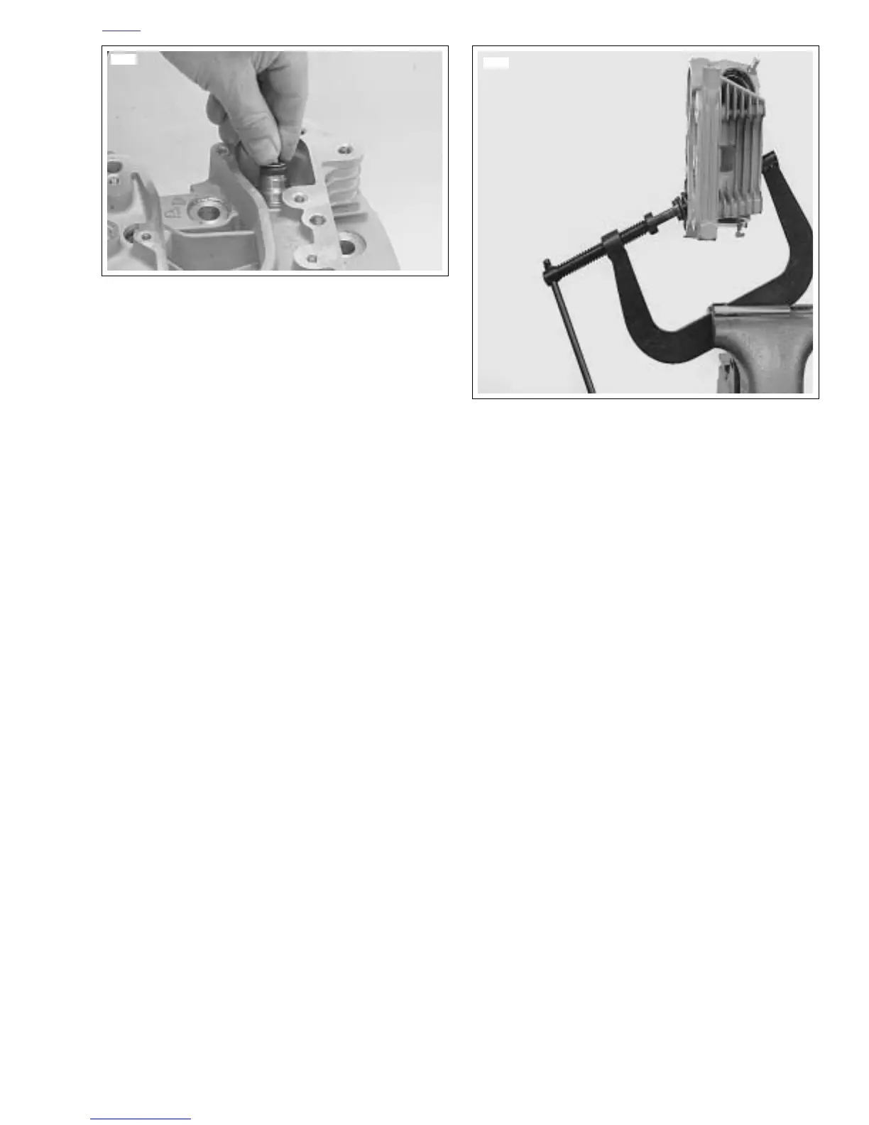
9. See Figure 3-79. Compress spring with VALVE SPRING
COMPRESSOR (Part No. HD-34736B).
NOTE
A single valve spring is used for each valve. The inner and
outer springs are combined into one tapered spring that is
progressively wound.
10. Insert valve keepers into upper collar, making sure they
engage grooves in valve stem.
11. Release and remove from VALVE SPRING COMPRES-
SOR.
12. Repeat Steps 4-11 for the remaining valve.
Figure 3-78. Valve Seal and Lower Collar Assembly
Installation
8705
Figure 3-79. Valve Spring Compressor
(Part No. HD-34736B)