2006 Buell Lightning: Engine 3-69
HOME
ASSEMBLY/INSTALLATION
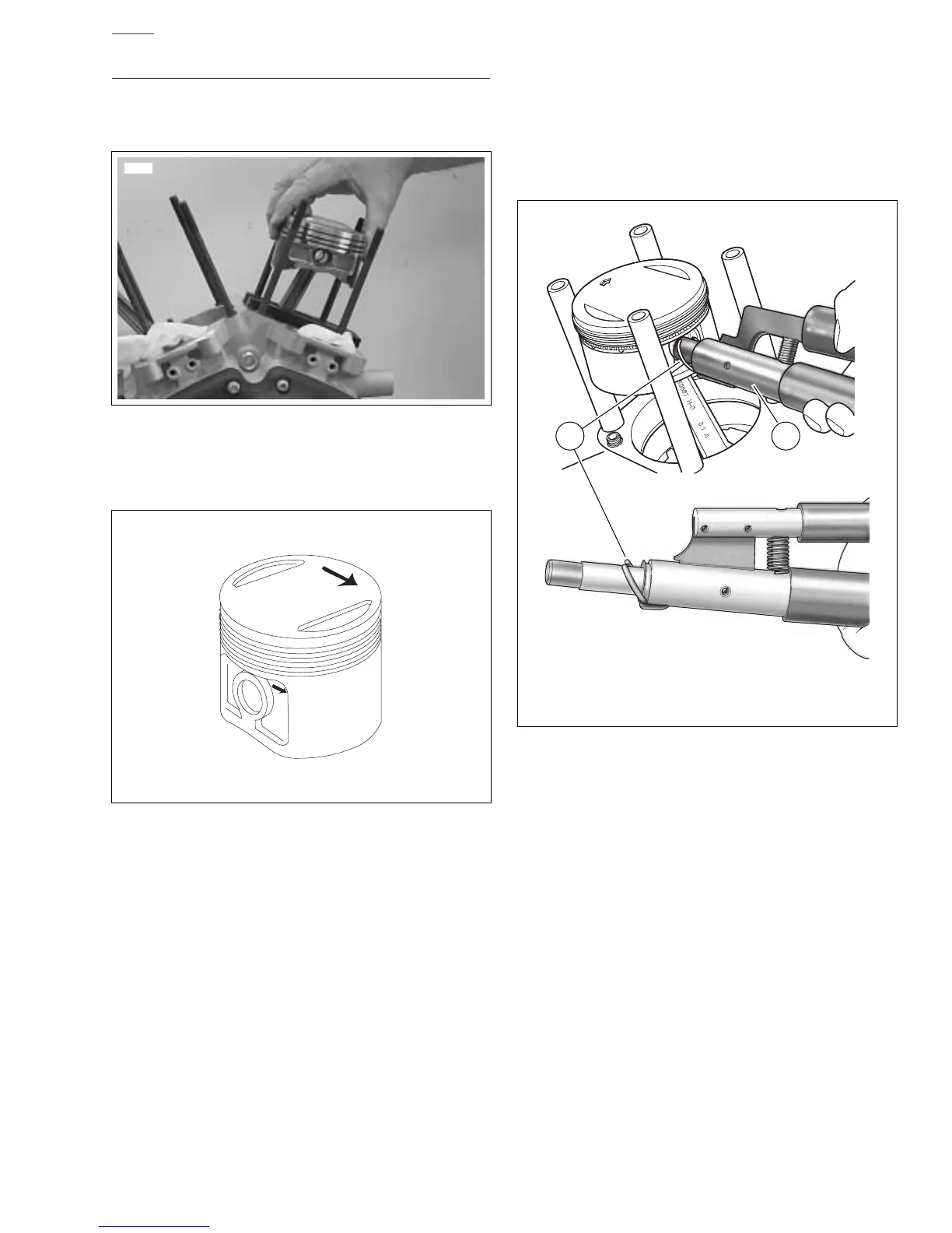
1. See Figure 3-101. Place PISTON SUPPORT PLATE
(Part No. HD-42322) in position as shown.
2. Install piston assembly over connecting rod.
NOTE
See Figure 3-102. Piston must be installed with the arrows
pointing towards the front of the engine.
3. Install piston pin.
NOTE
Always use new retaining ring. Make sure retaining ring
groove is clean and that ring seats firmly in groove. If it does
not, discard the ring. Never install a used retaining ring or a
new one if it has been installed and then removed for any rea-
son. A loosely installed ring will come out of the piston groove
and damage cylinder and piston beyond repair.
4. See Figure 3-103. Install new piston pin retaining rings
(1) using PISTON PIN RETAINING RING INSTALLER
(2) (Part No. HD-34623C). Place new retaining ring on
tool with gap pointing up.
NOTE
Make sure the ring groove is clean. Ring must be fully seated
in the groove with the gap away from the slot at the bottom.
Figure 3-101. Piston Support Plate
(Part No. HD-42322)
Figure 3-102. Piston Identification
8670
b0057d3x
Figure 3-103. Installing Piston Pin Circlip
b1002x3x
b1001x3x
1. Piston pin retaining ring
2. Piston pin retaining ring installer
(Part No. HD-34623C)
21