3-88 2006 Buell Lightning: Engine
HOME
REMOVAL/DISASSEMBLY
11WARNING1WARNING
Compressed air can pierce the skin and flying debris
from compressed air could cause serious eye injury.
Wear safety glasses when working with compressed air.
Never use your hand to check for air leaks or to deter-
mine air flow rates. (00061a)
1. See Figure 3-126. Thoroughly clean area around gear-
case cover and tappets. Blow loose dirt from crankcase
with compressed air.
2. Remove any parts that will interfere with gearcase disas-
sembly.
3. Remove push rods. See 3.6 CYLINDER HEAD.
4. Remove hydraulic lifters. See 3.17 HYDRAULIC LIFT-
ERS.
5. Check for minimum cam gear end play. Record readings.
6. Remove cam position sensor and rotor from gearcase
cover. See 4.31 CAM POSITION SENSOR AND
ROTOR.
7. Place a pan under gearcase to collect oil. Remove cover
screws. Carefully remove gearcase cover. Discard old
gasket.
NOTE
If cover does not come loose on removal of screws, tap lightly
with a plastic hammer. Never pry cover off.
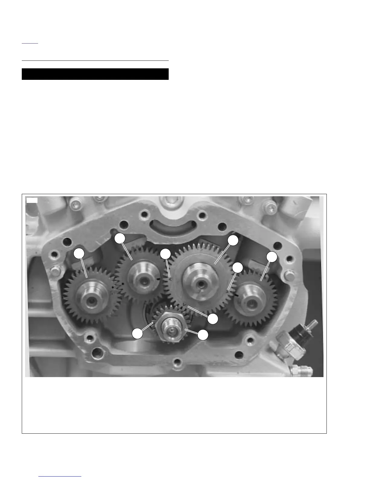
8. See Figure 3-127. Remove cam gears (1, 2, 3 & 4).
NOTE
Nut is secured by LOCTITE 262 (red)
on the nut threads.
9. Remove pinion nut (6). Slide pinion gear (5) and oil pump
drive gear (6) off pinion shaft.
NOTE
See Figure 3-127. The XB9SX timing marks are located on
the front intake cam assembly (2). Note the “V” marks.
Figure 3-127. Cam and Pinion Gear Location and Timing Mark Indexing
1. Front exhaust cam gear
2. Front intake cam gear
3. Rear intake cam gear
4. Rear exhaust cam gear
5. Pinion gear
6. Pinion nut
7. Timing V mark
1
2
3
4
5
6
8662a
7
7
7