4-30 2006 Buell Lightning: Fuel System
HOME
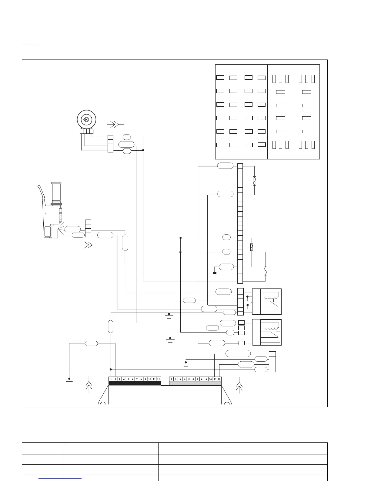
Figure 4-23. ECM Power Circuit
1
1
2
2
3
3
4
4
1
2
3
4
21
22
24
25
26
27
28
29
30
31
32
33
34
34
35
36
37
38
39
40
41
42
43
44
9
5
5
4
1
87
87A
30
85
86
19
15
14
11
87
87A
30
85
86
23
1
9
10
8
2
20
18
12
17
67
16
15
14
19
13
11
54
3
Ignition Start
Key Sw
39
40
41
42
43
44
33
34
35
36
37
38
21
22
23
24
25
26
28
29
30
31
32
27
Spare
Diode
Bk/Hn/Mflr
Fan
IGN
Acces.
Key Sw
Lights
ECM
Spare
Empty
Battery
Right Handlebar
Switch
GY/O
GY
Ignition
Relay
Key
Switch
Relay
Ignition
Fuse
Key Switch
Fuse
Ignition
Switch
Battery
Fuse
Electronic Control Module (ECM)
Connector
Connector
R
R
W/BK
R
R
R
R/BK
BK
BK
W/BK
GY/O
W/BK
R/BK
GY
GY
GY
BK
LT GN/R
V/R
To Battery
R/BK
R/BK
GY/O
b1077c4x
*ECM [10] Pin 1 also provides
power to fuel pump, both fuel
injectors and coil.
Fuse Block
&
Relay
Center
Top View
[33B]
[33A]
[10B]
[11B]
[11A]
[10A]
[22A]
[22B]
Data
Link
R/Y
BK
Table 4-13. Wire Harness Connectors in Figure 4-23.
NO. DESCRIPTION TYPE LOCATION
[10] ECM (black) 12-place Deutsch under seat
[22] right hand controls 4-place Multilock to the right of windscreen
[95] clutch switch 2-place Multilock to the left of windscreen