2006 Buell Lightning: Starter 5-19
HOME
ASSEMBLY
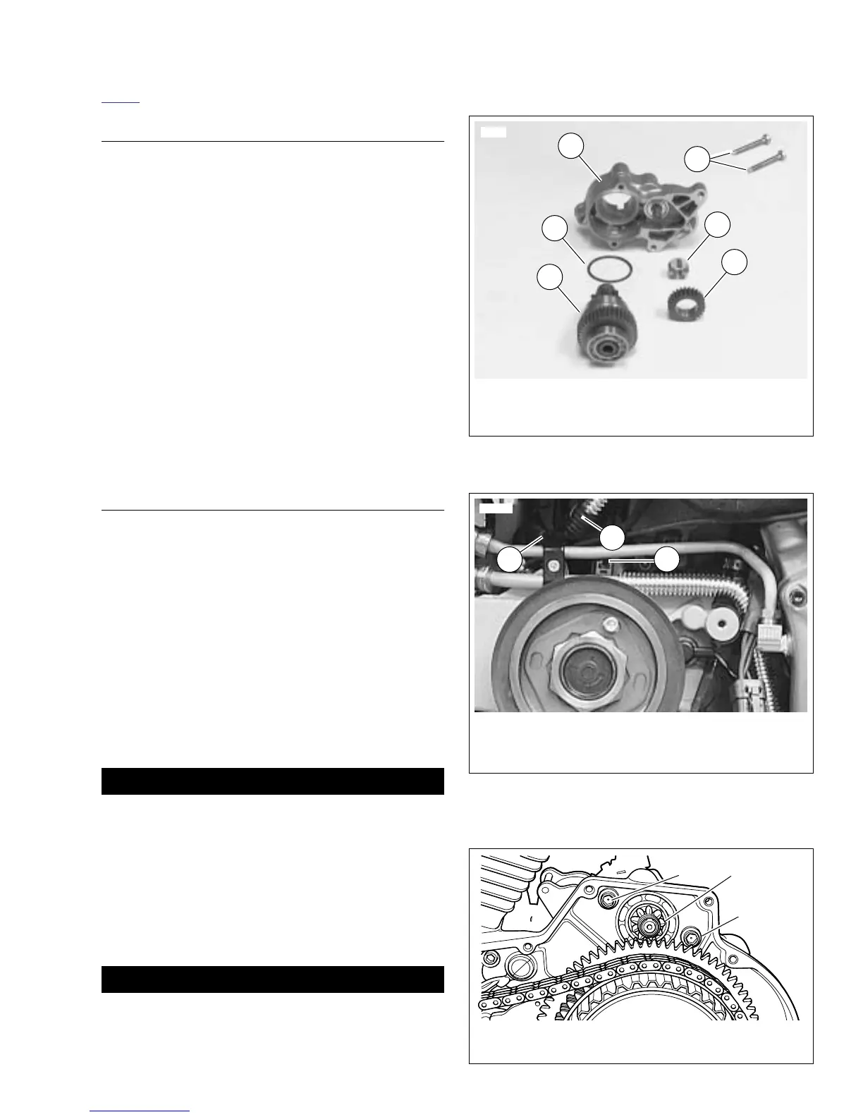
1. See Figure 5-24. Clean, inspect and lubricate drive
assembly components. Lubricate parts with high temper-
ature grease, such as LUBRIPLATE 110.
2. See Figure 5-27. When installing drive assembly compo-
nents, open end of idler bearing cage (15) faces toward
solenoid.
3. When installing drive housing (10) to solenoid housing
(11), use
new
o-ring (16). Be sure to install return spring
(17) and ball (18).
4. Lubricate armature bearings (8) with high temperature
grease, such as LUBRIPLATE 110. Install armature (6)
and field frame (7) to solenoid housing (11).
5. Install brushes and brush holder (4).
6. Install o-rings (23). Attach end cover (3) with end cover
screws and o-rings (2).
7. Install thru-bolts (1).
8. Attach field wire (22) to solenoid housing (11) with field
wire nut and washer (24) (metric). Replace rubber boot.
INSTALLATION
1. Install starter and starter gasket from the gearcase cover
side.
2. See Figure 5-25. Connect wiring to starter.
a. Connect solenoid wire (3).
b. Attach positive battery cable (2) ring terminal to stud
with fastener and washer.
c. Install nut and washer (1) (metric). Tighten nut to 60-
85
in-lbs
(7-10 Nm).
d. Replace protective boot.
3. See Figure 5-26. Install both starter mounting bolts and
washers. Tighten to 13-20 ft-lbs (18-27 Nm).
4. Install sprocket cover. See 2.33 SPROCKET COVER.
5. Install primary cover. See 6.2 PRIMARY COVER.
1WARNING1WARNING
Connect positive (+) battery cable first. If positive (+)
cable should contact ground with negative (-) cable con-
nected, the resulting sparks can cause a battery explo-
sion, which could result in death or serious injury.
(00068a)
6. Install positive battery cable (red) to positive terminal of
battery. Tighten to 72-96
in-lbs
(8-11 Nm).
7. Connect negative battery cable. Tighten to 72-96
in-lbs
(8-11 Nm).
1WARNING1WARNING
After installing seat, pull upward on front of seat to be
sure it is in locked position. While riding, a loose seat can
shift causing loss of control, which could result in death
or serious injury. (00070a)
8. Install seat. See 2.43 SEAT.
Figure 5-24. Starter Drive Assembly
Figure 5-25. Starter Wires
(protective boot not shown)
Figure 5-26. Starter Mounting