6-6 2006 Buell Lightning: Drive/Transmission
HOME
10. Fill transmission to proper level with fresh lubricant. See
1.8 CLUTCH.
11. See Figure 6-7. Install clutch inspection cover (4) with
new
gasket and three TORX screws with washers.
Tighten screws in a crosswise pattern to 84-108
in-lbs
(9.5-12.2 Nm).
12. See Figure 6-8. Install rubber washer and engine shift
lever assembly (1).
13. After applying LOCTITE 272, install flange bolt (5) and
shift pedal to primary cover, and tighten to 22-24 ft-lbs
(30-32.5Nm).
14. After applying LOCTITE 272 (red), tighten engine shift
lever pinch screw to 48-60
in-lbs
(5.4-6.8 Nm).
15. If the shift linkage assembly (8) was removed for any rea-
son, apply Loctite 272 to fasteners and tighten to 36-60
in-lbs
(4-6.8 Nm). Adjust to rider comfort.
16. Install left footpeg support bracket. See 2.32 FOOTPEG,
HEEL GUARD AND MOUNT.
17. Install chin fairing. See 2.36 CHIN FAIRING.
11WARNING1WARNING
Connect positive (+) battery cable first. If positive (+)
cable should contact ground with negative (-) cable con-
nected, the resulting sparks can cause a battery explo-
sion, which could result in death or serious injury.
(00068a)
18. Connect negative battery cable to battery terminal.
Tighten fastener to 72-96
in-lbs
(8-11 Nm).
11WARNING1WARNING
After installing seat, pull upward on front of seat to be
sure it is in locked position. While riding, a loose seat can
shift causing loss of control, which could result in death
or serious injury. (00070a)
19. Install seat. See 2.43 SEAT.
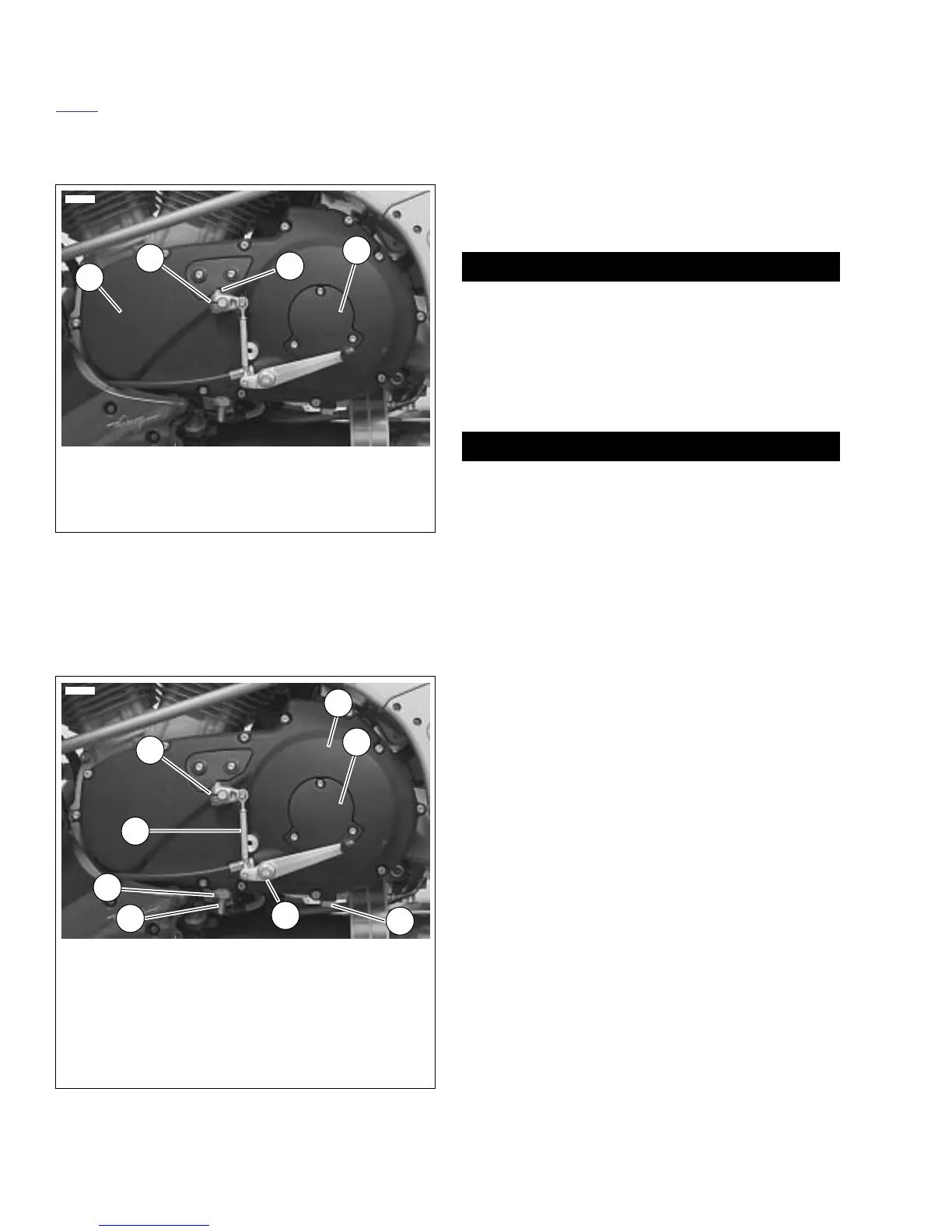
Figure 6-7. Installing Primary Cover
Figure 6-8. Installing Shift Linkage
1. Primary cover
2. Lever, engine
3. Engine lever pinch screw
4. Clutch inspection cover
4
1
3
2
8806
1. Engine shift lever
2. Primary cover
3. Clutch inspection cover
4. Drain plug
5. Flange head bolt
6. Chain adjuster screw
7. Locknut
8. Shift linkage assembly
3
2
4
7
6
1
8806
5
8