6-12 2006 Buell Lightning: Drive/Transmission
HOME
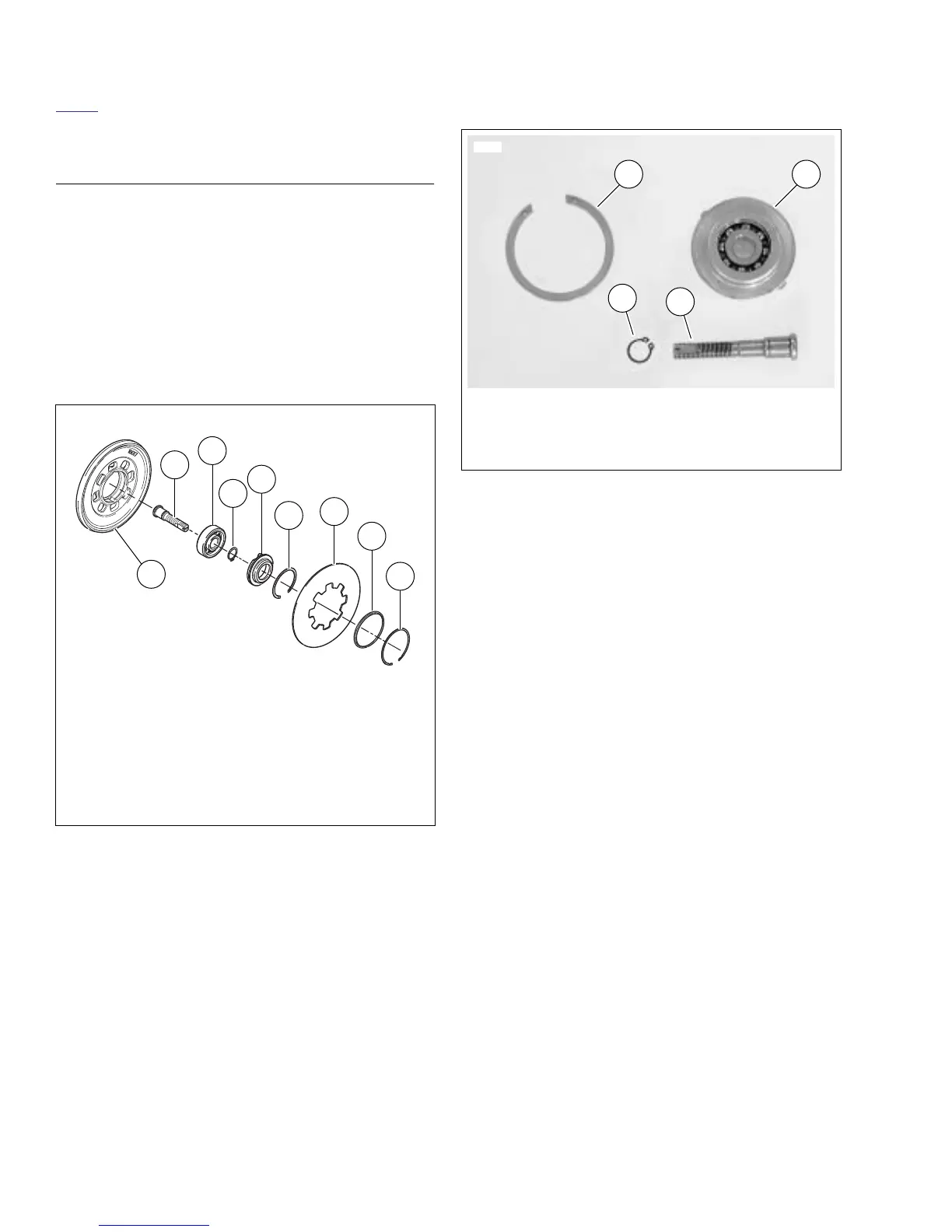
ADJUSTING SCREW DISASSEM-
BLY/ASSEMBLY
1. See Figure 6-15. Remove adjusting screw assembly.
a. Remove large retaining ring.
b. Remove adjusting screw assembly from pressure
plate.
2. If necessary, disassemble adjusting screw assembly.
a. Remove and discard small retaining ring (6).
b. Separate the adjusting screw (8) from the bearing
(7) and release plate (5).
c. Remove bearing (7) from release plate (5).
3. Replace components as required and reassemble
adjusting screw assembly in reverse order.
4. Install adjusting screw assembly into pressure plate.
a. See Figure 6-37. Align two tabs on perimeter of
release plate with corresponding recesses (3) in
pressure plate.
b. Secure the adjusting screw assembly with
new
retaining ring.
Figure 6-15. Adjusting Screw Assembly
1
2
3
4
5
6
7
8
9
1. Retaining ring
2. Spring seat
3. Diaphragm Spring
4. Retaining ring
5. Release plate
6. Retaining ring
7. Bearing
8. Adjusting screw
9. Pressure plate
b1062x6x
Figure 6-16. Adjusting Screw Assembly
6251
1
1. Retaining ring
2. Bearing and release plate
3. Retaining ring
4. Adjusting screw
2
3
4