7-28 2006 Buell Lightning: Electrical
HOME
Current and Voltage Output Test
1. Connect load tester.
a. Connect negative and positive leads to battery ter-
minals.
b. See Figure 7-30. Place load tester induction pickup
over positive regulator cable.
NOTE
Do not leave any load switch turned on for more than 20 sec-
onds or overheating and tester damage are possible.
2. Run the engine at 3000 RPM. Increase the load as
required to obtain a constant 13.0 VDC.
3. The current output should be 34-38 amps. Make note of
measurement for use in TOTAL CURRENT DRAW TEST.
NOTE
Rider’s habits may require output test at lower RPM.
Voltage Output Test
1. See Figure 7-30. After removing the load, read the load
tester voltage meter.
a. If voltage to the battery is not more than 15 VDC,
voltage output is within specifications. Investigate
other possible problems. See TROUBLESHOOT-
ING in this section.
b. If voltage is higher, regulator is not functioning prop-
erly.
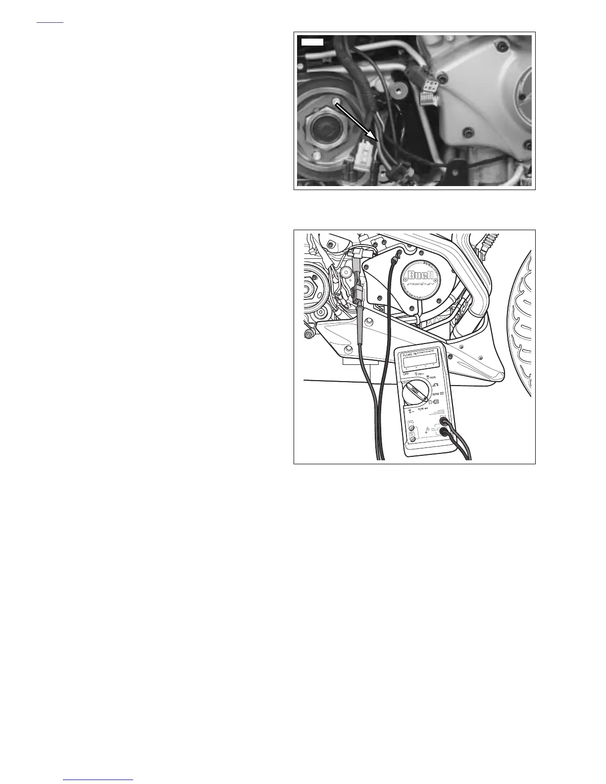
Stator Check
1. Turn ignition key switch to OFF.
2. See Figure 7-31. Connect an ohmmeter.
a. Locate voltage regulator connector [46] under
sprocket cover. See 7.26 SPROCKET COVER WIR-
ING. Disconnect from alternator stator wiring.
b. Insert one ohmmeter lead into a stator socket.
c. Attach the other lead to a suitable ground.
3. Test for continuity with ohmmeter set on the RX1 scale.
a. A good stator will show no continuity (
∞
ohms)
across
all
stator sockets and ground.
b. Any other reading indicates a grounded stator which
must be replaced.
4. See Figure 7-32. Remove ground lead. Check resistance
across stator sockets 1-2, 2-3 and 3-1.
5. Test for resistance with ohmmeter set on the RX1 scale.
a. Resistance across the stator sockets should be 0.1-
0.3 ohms.
b. If the resistance is lower, the stator is damaged and
must be replaced.
NOTE
Verify that meter reads 0 ohms when probes are shorted
together. If not, subtract lowest value to resistance value of
stator.
Figure 7-30. Positive Regulator Cable (red wire)
Figure 7-31. Test for Grounded Stator
11977a
b0996x7x