7-78 2006 Buell Lightning: Electrical
HOME
REMOVAL
1. Remove sprocket cover. See 2.33 SPROCKET COVER.
2. See Figure 7-100. Disconnect appropriate connector(s).
INSTALLATION
NOTES
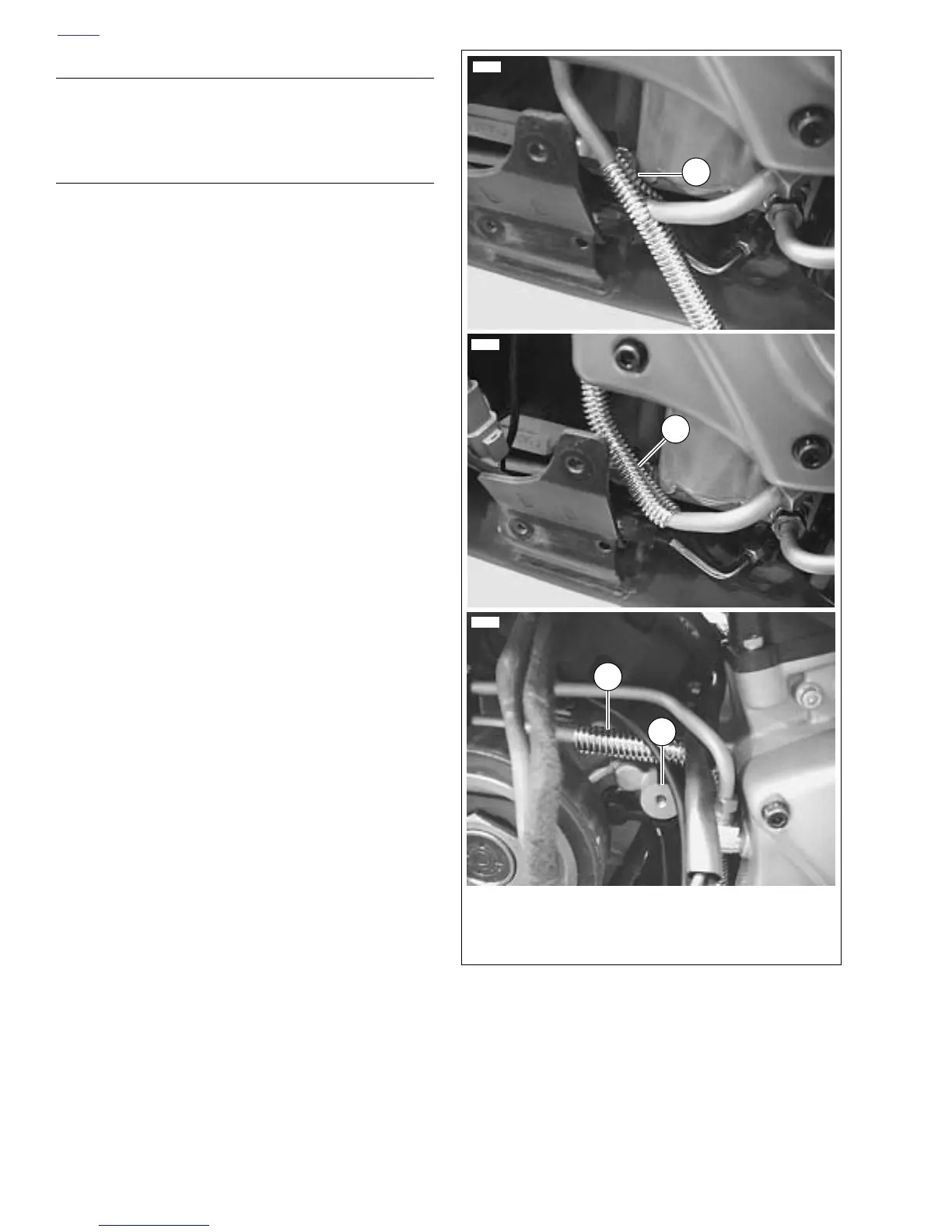
See Figure 7-101. Convolute covering the return oil line
should have the seam rotated to the back side of the oil line
away from wiring.
1. Route the vehicle speed sensor wiring behind the starter
trigger wire and secure in place with a cable strap.
2. See Figure 7-100. Route oil pressure switch wiring (9)
from main harness (5), to oil pressure switch located on
front of engine and connect to the oil pressure switch.
NOTES
● Stator connector wiring is installed over oil pressure
switch wiring.
● See Figure 7-100. Make sure the stator wire bundle is
behind the oil breather fitting (6).
3. See Figure 7-100. Place the larger black and red wires in
the harness up against the front of the upper sprocket
cover boss behind the vent line fitting in the cam cover
and connect the (2-pin) voltage regulator (1).
Figure 7-101. Convoluted Covering for Oil Return Line
12008
12009
12010
1. Reflective convolute covering with seam
2. Covering in place on bottom of return line
3. Covering in place on top of return line
4. Sprocket cover boss
3
1
2
4