7-80 2006 Buell Lightning: Electrical
HOME
11. See Figure 7-105. Position the cam position sensor wire
bundle and the voltage regulator wire bundle inboard,
then push the wire bundle up against the return oil line
and cable strap them to the return oil line.
12. See Figure 7-106. Capture the main wire harness bun-
dle, the vehicle speed sensor lead, the stator bundle, and
the muffler actuator cable (if applicable) to the oil return
line with a cable strap.
13. See Figure 7-107. Connect the vehicle speed sensor
last.
NOTES
● The vehicle speed sensor is positioned high in the bun-
dle in order for the front sprocket cover to conform to the
additional components.
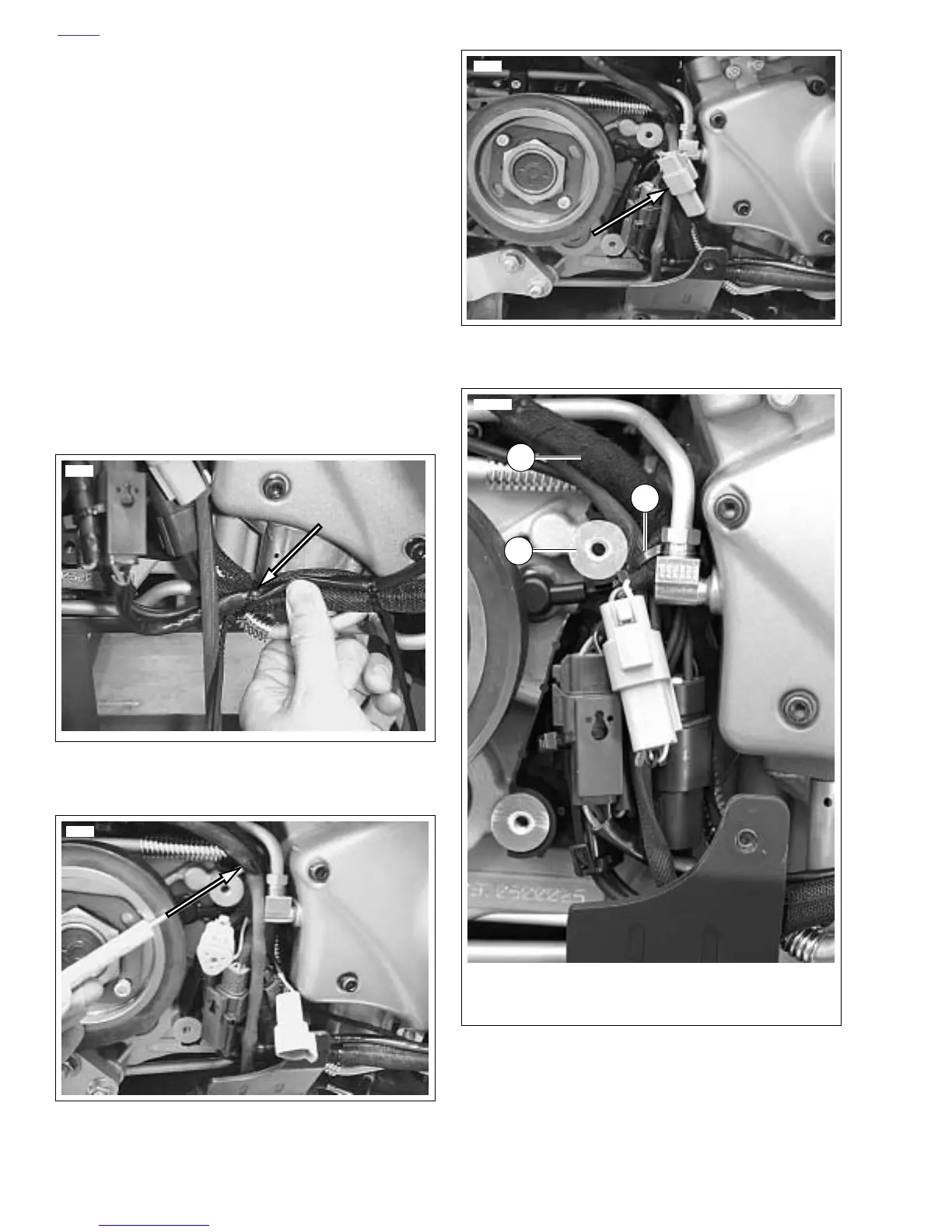
● See Figure 7-108. Make sure main harness (2) is routed
around sprocket cover boss (1).
14. Install sprocket cover. See 2.33 SPROCKET COVER.
Figure 7-105. Cable Strap Wire Bundle to Return Oil Line
Figure 7-106. Cable Strap Wire Bundle to Return Oil Line,
Upper Part of Sprocket Cover
12007
12014
Figure 7-107. Vehicle Speed Sensor
Figure 7-108. Correct Location for Sprocket Cover Wiring
12015
1. Sprocket cover boss
2. Main harness
3. Cable strap securing main harness wiring
3
1
11970a
2