Appendix A Assembly Drawings Page A-30
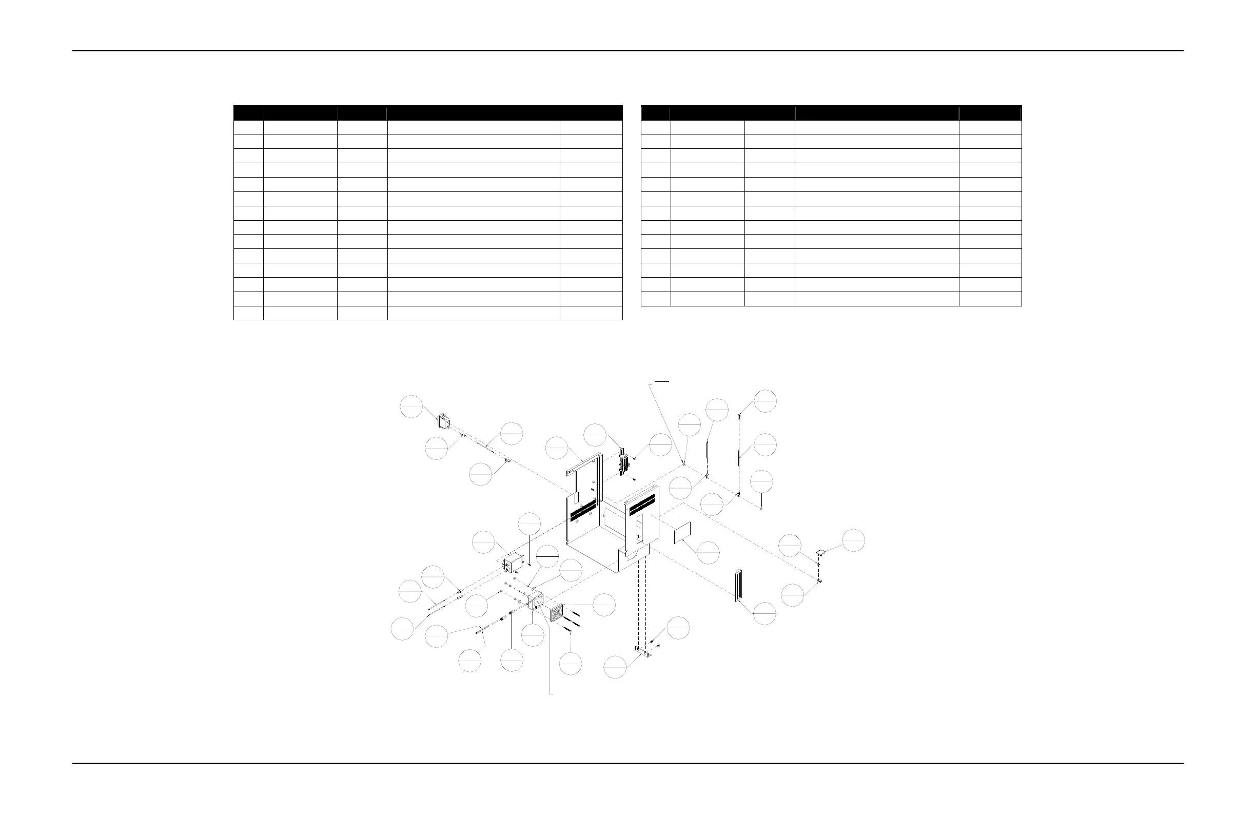
Table A-26: Tabber Back Cover Assembly (9101244A)
Item Part Number Quantity Description Reference
Item Part Number Quantity Description Reference
1 403080 4 Screw, FHCS, 8-32 UNC X 1 1/2 in 15 609102 2 Marrette, Black
2 403510 4 Screw, BHCS, 8-32 UNC x 1/4" 16 609110 5 Connector, Push-on, Blue
3 405520 2 Screw, BHCS, 1/4-20 UNC, 3/8" 17 609114 2 Ring Tongue Terminal, #10
4 420007 5 Nut, 8-32 UNC 18 615140 1 Lashing Tie
5 420008 2 Nut, 10-32 UNF 19 9100343 1 Fan, 12VDC
6 439005 4 Lockwasher, No.8 20 9100674 1 Filter, Corcom, 10 A
7 440006 4 Washer, #8, 1/2" O.D. x 0.05" Thick 21 9100728 1 Tie Anchor Mount, #8 Screw
8 603300 1 Switch, Breaker, 5A, 1 Pole 22 9101244 1 Tabber Head Back Cover
9 606000 2 Wire #16, Black, Hookup (10" Long) 23 9101575A 1 Tabber Terminal Block Assembly Page A-34
10 606005-10 1 Wire #16, Green, Hookup (10" Long) 24 9101620 1 Mounting Bracket, Slide Rail
11 606005-15 1 Wire #16, Green, Hookup (15" Long) 25 9101627 1 Buskro Serial Number Label
12 606009 1 Wire #16, White, Hookup (10" Long) 26 9101640 1 Handle, Panel Snap Style
13 606020 1 Wire, #18, Black, Hookup (10" Long) 27 9101655 1 Filter, 12 VDC Fan
14 606022 1 Wire, #18, Red, Hookup (10" Long)
Figure A-27:
Tabber Back Cover Assembly (9101244A)
24
1
3
2
22
1
9
2
21
1
4
5
18
1
8
1
16
5
16
5
26
1
25
1
17
2
17
2
16
5
11
1
5
2
14
1
13
1
5
2
19
1
20
1
16
5
12
1
9
2
2
4
23
1
10
1
2
4
27
1
15
2
4
5
6
4
7
4
1
4
NOTE: Attach the ring terminal from
Cable #1 of 9101134A before the first
nut is attached. This is a chassis ground.
FAN SHOULD BLOW AIR INTO
THE TABBER HEADTO COOL THE
2-PHASE STEPPER MOTOR.
Buskro Ltd. BK730-2 Tabber