Chapter 2 BK730-2 Base Page 2-24
between the two rollers is uneven. Conversely, a tight gap setting will cause the crease
roller to act as a knife shearing the tab into two pieces.
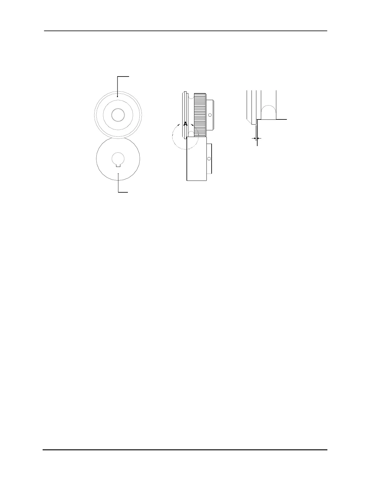
Crease Roller
Pinch Roller
VIEW A
0.5 mm
Figure 2-11: Crease/Pinch Roller Combination
To set the pinch rollers:
The objective of this adjustment is to align the outer edge of the pinch rollers with the
material side guides to ensure that the tab fold produced by the crease roller is as close to
the product’s edge as possible.
1. Move the tabbing head peel point away from the front side’s pinch rollers.
2. Obtain a clear, unobstructed access to the pinch rollers by pivoting the upper
transport assembly upwards.
3. Place a ruler or a straight edge against the front material guide’s inner edge as per
Figure 2-12.
4. Loosen the 10-32 UNF set screw of both of the front side’s pinch rollers using a
3/32” hex key ensuring that they are free to move laterally on the shaft. This
setscrew is located on the roller’s shoulder.
5. Grip the first pinch roller and move it until its outer edge aligns with the ruler.
Secure it on the shaft by re-tightening its setscrew. Repeat for the second pinch
roller.
6. Repeat steps 3 to 5 for the pinch rollers situated on the rear of the Tabber/Labeler.
Buskro Ltd. BK730-2 Tabber