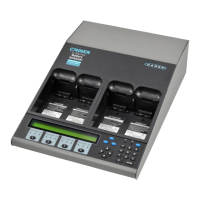
Component Function
Numeric keypad
Enter passwords or numeric values in a C-Code.
Direction keys
Navigate menus, move between fields, select values, view service
details.
LED indicators
View current status of batteries in service (activated when a service
starts).
Ready (Green): Service complete and/or battery has passed.
Fail (Red): Battery service has failed or there is a fault.
Run (Yellow): Service in progress.
LCD display
2x40 character screen to display information on each station and its
details, to view Menu items.
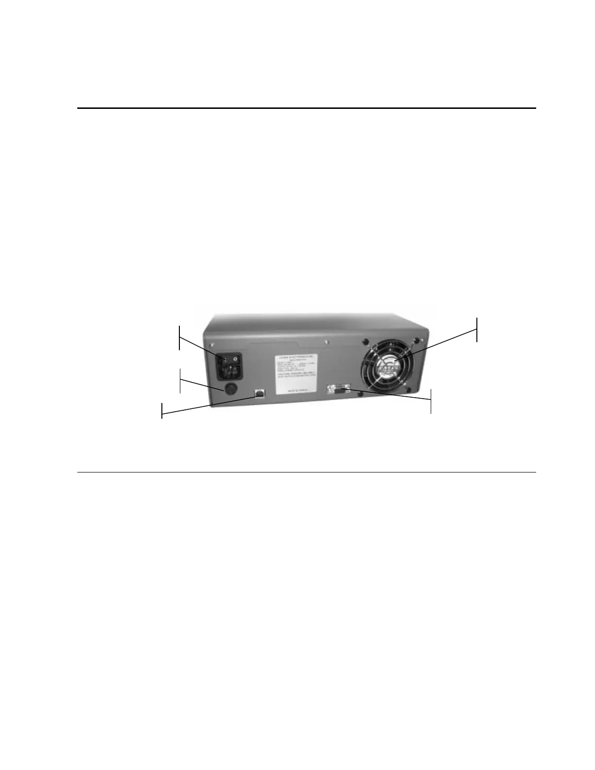
Figure 3: Rear panel of Cadex battery analyzer
Component Function
On/Off Power Switch
Turns the analyzer On and Off.
IEC 320 AC Input
Connect the unit to an AC electrical power source with the IEC 320
power cord (North American version supplied).
RS232 serial port
(9-pin) & USB Port
To connect to the serial port of a computer to upgrade the firmware,
to use BatteryShop or to monitor data, or to print to a label printer.
Cooling Fan
Operates continuously to keep the interior of the analyzer at an
optimum working temperature.
Do not restrict the airflow of the analyzer. Leave the fan opening
clear. Fan operation is automatic.
Primary Input Fuse
Protects the unit from internal short circuits. Can be replaced (see
Replacing the Primary (Input) Fuse, page 100).
On/Off Power Switch
& A/C Input
RS232 serial port
Cooling Fan
Primary Input Fuse
USB Port
 Loading...