System Planning 75
l The bottom LPU can be connected to the drop cable from the ODU.
l The bottom LPU is within 600 mm (24 in) of the point at which the drop cable enters the building,
enclosure or equipment room within a larger building.
l The bottom LPU can be bonded to the grounding system.
Deployment Considerations
This section provides a brief information specific to the deployment of 60 GHz cnWave series of
products. This section covers the following topics:
l Key deployment guidelines
l Sector and alignment
l Minimum CN spacing
l Near-far radio
l Early weak interference
l Avoiding the tight angle deployment
l Avoiding the straight line interference
l When two V5000 devices are co-located at a site
l Polarity
l Link Adaptation and Transmit Power Control (LATPC)
Key deployment guidelines
Following are some of the key guidelines that you must consider for the deployment of 60 GHz cnWave
series of products:
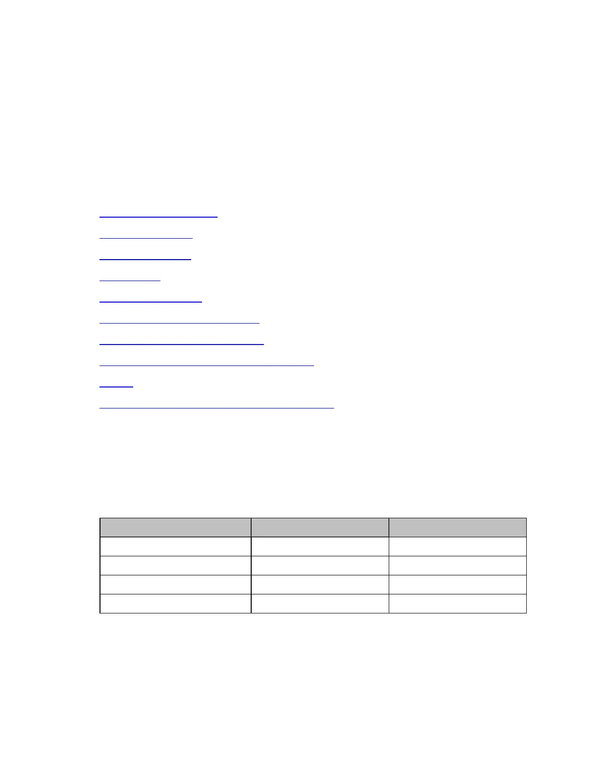
l Mounting accuracy: Cambium Networks has three different Stock Keeping Units (SKUs). These
three SKUs have different requirements in terms of alignment coverage, as shown in Table 30.
Table 30: Details of alignment coverage - 60 GHz cnWave products
60 GHz cnWave product version Azimuth (in degrees) Elevation (in degrees)
V5000 +/-70 per sector +/-20
V3000 +/-2 +/-1
V2000 +/-10 +/-4.5
V1000 +/-40 +/-20
l Minimum deployment distance: A typical minimum deployment distance is based on the maximum
receive signal strength of -40 dBm, as listed: