System Planning 77
Maximize the pole or box height during the deployment. This action minimizes the ground bounce and
avoids channel fluctuations, especially for links with long distances. The suggested height is >5m.
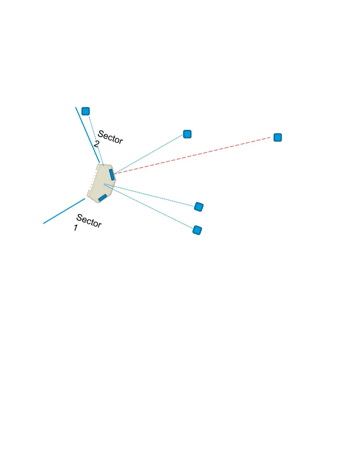
You must consider the orientation of a DN node in P2MP. For example, orient the V5000 to the boresight
of the RF tile to the longest link (where possible). The optimal beam angle to achieve the maximum
antenna gain is at boresight of the active tile face (as shown in Figure 51 using the Red dotted line).
Figure 51:
Optimal beam angle
Consider the following deployment specific points:
l Avoid sticking any metallic labels on the radome.
l The 60 GHz cnWave antenna tiles are located on the four marked faces.
l The GPS antenna is located at the middle of the top face of the radome that is pointed to the sky.
Minimum CN spacing
Consider the following key points for the minimum CN spacing at a sector intersection:
l Up to 15 CNs can be installed on a single sector. Time Division Multiple Access scheme (TDMA)
dynamically schedules the time slots for each wireless link on an access point, such that they do
not interfere with one another.
l When CNs are installed in multiple sectors, more than one CN can be talking at a given time as the
sectors have independent schedulers.
If both CNs installed in different sectors are located within the highlighted 20 degree range, then
configure the two sectors to be on different channels to avoid interference.
Figure 52 shows the minimum CN spacing at a sector intersection.