Installation 96
Siting radios
Radios are not designed to survive direct lightning strikes. For this reason they must be installed in Zone
B as defined in
Lightning protection zones
. Mounting in Zone A may put equipment, structures, and life at
risk.
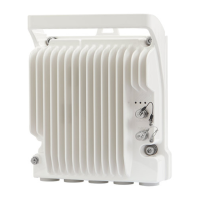
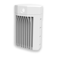
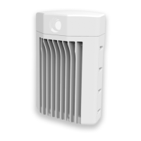
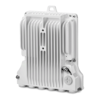
60 GHz cnWave radios and mounting bracket options
The 60 GHz cnWave series supports eight mounting bracket options. Select the optimum mounting
bracket arrangement based on the ODU type and the choice of wall or pole mounting. The wall mount
plate for V1000 and V5000 are included with the ODU. Order the remaining brackets separately.
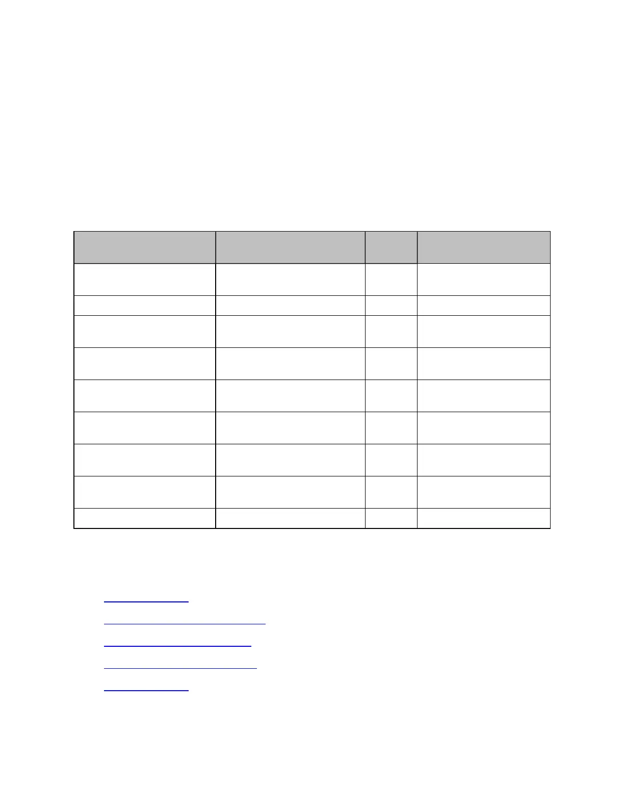
Table 35: ODU mounting bracket part numbers
Bracket Pole diameter ODU
variants
Bracket part number
V1000 pole mount 25 mm to 70 mm (1 inch to
2.75 inches)
V1000 Included with V1000
V1000 wall mount Wall mount V1000 Included with V1000
V1000 adjustable pole mount 25 mm to 70 mm (1 inch to
2.75 inches)
V1000 N000900L022A
V2000 Adjustable pole
mount
25 mm to 70 mm (1 inch to
2.75 inches)
V2000 Included with V2000
V3000 precision bracket 25 mm to 70 mm (1 inch to
2.75 inches)
V3000 C000000L125A
V3000 tilt bracket assembly 25 mm to 70 mm (1 inch to
2.75 inches)
V3000,
V5000
N000045L002A
V3000 tilt bracket assembly
with band clamps
The diameter range depends
on the clamps used.
V3000,
V5000
N000045L002A + third-
party band clamps
V5000 pole mount 25 mm to 70 mm (1 inch to
2.75 inches)
V5000 C000000L137A
V5000 wall mount Wall mount V5000 C000000L136A
Installing the cnWave radio nodes
To install the radio, use the following procedure and guidelines:
1. Typical installation
2. ODU interface with LPU on the pole
3. SFP and Aux Ethernet interfaces
4. Attach ground cables to the radio
5. Mounting the ODU