E568-8002/Shaved gear tooth due to overloading with friction from
sliding while the estrangement rack is moving (Staple-Q1/W1/
Booklet-Q1/W1/Saddle-AM2/AN2/Finisher-AM1/AN1)
[Symptom/Question]
E568-8002 and shaving on the gear tooth may occur in the machine earlier than the following countermeasure cut-in serial
numbers in factory.
- E568-8002 : Feed Roller HP error
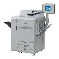
[Cause]
While the feed roller shaft is moving up and down to detect home position, if the estrangement rack [1] that holds the feed roller
shaft inclines, the load from sliding increases and the feed roller shaft becomes unable to go back to home position, and this
brings the aforementioned symptom.
[Remedy/Answer]
When the above-mentioned symptom occurs, perform the work either A) Replacing the upper feeder assembly with the new type
or B) Applying the grease to the feed assembly.
A) Replacing the upper feeder assembly with the new type
Prepare the new-type upper feeder assembly for each machine and perform the work by following the steps below.
A-1) Refer to Service Manual (4. Parts Replacement and Cleaning > Feed Assembly) and remove the delivery static eliminator
and the upper feeder assembly.
A-2) Replace the upper feeder assembly with the new type.
B) Applying the grease to the feed assembly
Prepare Molykote EM-50L (HY9-0007-000) and e-rings (XD9-0135-000, x5pcs) and perform the work following the steps below:
B-1) Refer to the service manual (4. Parts Replacement and Cleaning > Feed Assembly) and remove the delivery static eliminator
and the upper cover of the upper feeder assembly.
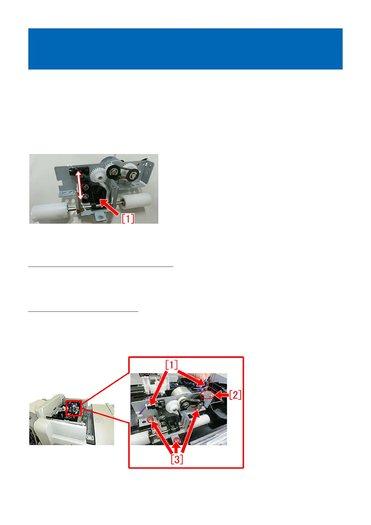
B-2) Disconnect the connectors [1] (x2pcs) and remove the screws (x2pcs) for grounding [2] and the screws [3] (x3pcs) to detach
the feed assembly.
B-3) Remove the estrangement rack [1] in the following order:
B-3-1) Remove the compression springs [2] (x2pcs).
224