INSTALLATION 29
TO CONNECT POWER
1. Connect the recessed end of the imagePRESS Server power cable to the power connector on
the back of the imagePRESS Server (see Figure 5 on page 28).
2. Connect the other end of the imagePRESS Server power cable to a wall outlet.
TO CONNECT TO THE COPIER
1. Make sure that the imagePRESS Server and the copier are powered off.
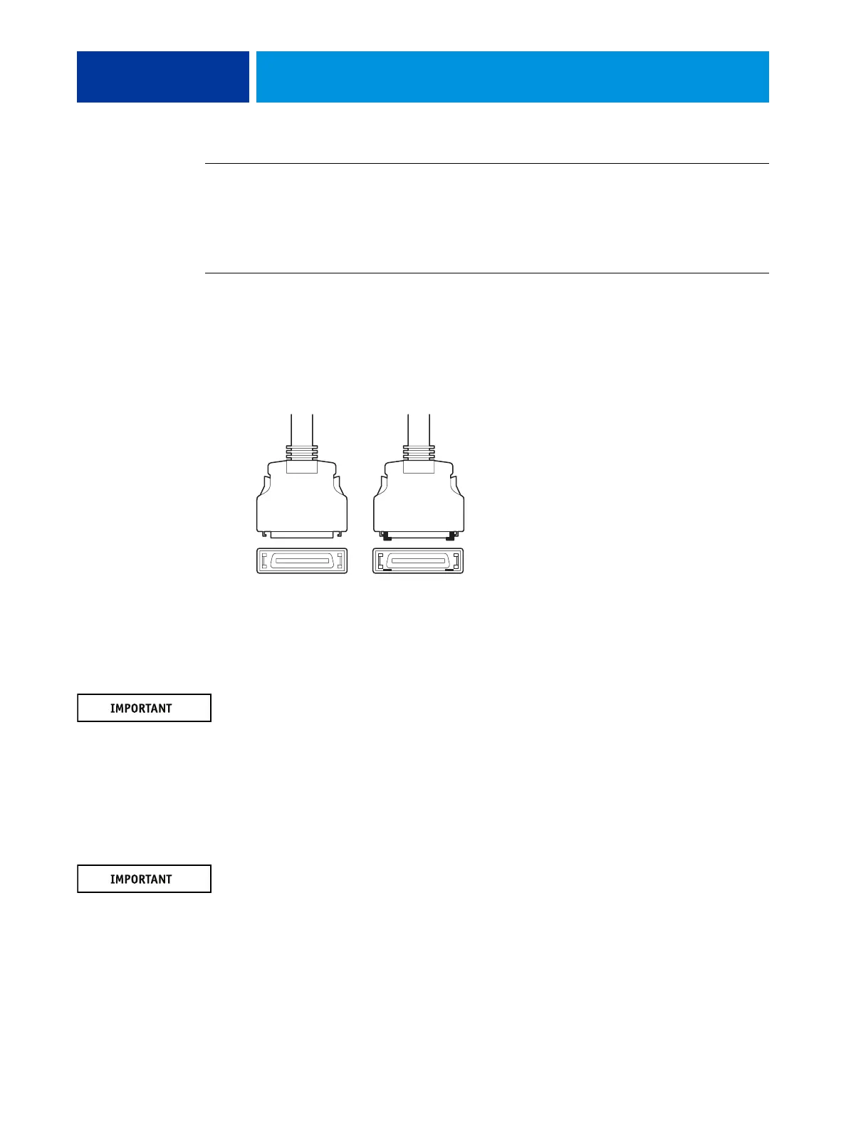
2. Locate the two imagePRESS Server copier interface cables, and identify the keyed and
unkeyed connector ends on each cable.
Each cable has one keyed connector and one unkeyed connector.
FIGURE 6: Copier interface cable connections
3. Connect the copier interface cables to the interface ports on the copier.
4. Connect the other ends of the cables to their corresponding ports on the imagePRESS Server.
Each cable connector is designed to fit only one way when properly oriented. If a cable
connector does not fit into an interface port, change the orientation of the cable. Do not force
a connection that is mis-keyed. Doing so may permanently damage the port or the cable (see
Figure 5 on page 28).
5. Connect one end of the Command/Status Ethernet Crossover cable to the lower RJ-45 port on
the back of the imagePRESS Server.
6. Connect the other end of the Command/Status Ethernet Crossover cable to the RJ-45 port on
the copier.
The Command/Status Ethernet Crossover cable and the straight-through Ethernet network
cable included with the imagePRESS Server look similar, but are not interchangeable. Make
sure that you attach the Command/Status Ethernet Crossover cable to the lower RJ-45 port
on the imagePRESS Server back panel (see page 28).
Unkeyed Keyed