SERVICE PROCEDURES 48
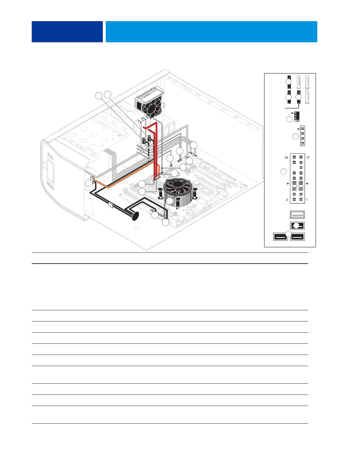
FIGURE 14: Power and data cable connections in the imagePRESS Server
Cable key From To
1. Power supply cable Power supply a. CPU power connector (PW1)
b. Motherboard power connector (PW2)
c. DVD drive power connector (combined with data)
d. HDD 2 power connector
e. HDD 1 power connector
2. Front panel USB port cables Front panel Motherboard connectors J22, J35 (see detail above)
3. UIB cable User Interface Board Motherboard connector J38 (see detail above)
4. Power and reset cables Front panel Motherboard connector JP4 (see detail above)
5. Speaker cable Front panel Motherboard connector J40 (see detail above)
6. Front panel fan cable Front panel fan Motherboard connector FAN 4
7. DVD drive power/data
combo cable
DVD drive Motherboard connector SATA 1 (see detail above)
8. HDD 1 data cable HDD 1 (Bottom drive in bracket) Motherboard connector SATA 2 (see detail above)
9. HDD 2 data cable HDD 2 (Top drive in bracket) Motherboard connector SATA 3 (see detail above)
10. CPU fan cable CPU fan Motherboard connector FAN 1 (If present, keep the
cable cover on the CPU fan cable.)
1b
1c
10
5
NOTE: Power supply, DIMMs,
and copier interface board
are
not shown.
87
DVD drive
(SATA 1)
HDD 1
(SATA 2)
HDD 2
(SATA 3)
FAN 4
J40
Speaker
Reset
Power
J22
Front panel USB port cables
J35
J38
JP4
UIB cable
1a
8
4
9
7
6
4
2
3
5
6
1d
1e
3
7 9
8
2