SERVICE PROCEDURES 46
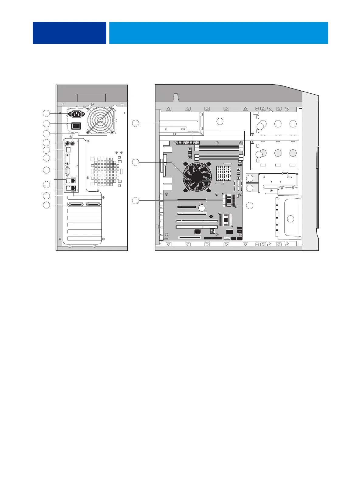
FIGURE 12: Back panel and internal side view
Key
1. Power cable connector
2. Power switch, back panel
3. Not used
4. Not used
5. USB ports (x2)
6. Not used
7. Monitor (option)
8. USB ports (x4)
9. Top = Network; Bottom = Command/Status port
10. Copier interface board (J12)
11. Power supply
12. CPU cooling assembly
13. DIMM slots
14. DVD drive
15. Removable drive (option)
16. HDD 2 in bracket
17. HDD 1 in bracket
18. Motherboard
19. Front fan
NOTE: Cables, UIB, or front panel USB ports are not shown.
1
3
4
5
6
7
8
17
14
15
19
13
9
18
12
11
10
10
2
16